
Numerically controlled lathe clamp assembly for machining rotary pipe joints with balls and machining method thereof

A technology of rotating pipe joints and CNC lathes, which is applied in the direction of manufacturing tools, metal processing equipment, metal processing machinery parts, etc., and can solve problems such as difficulty in guaranteeing, poor processing accuracy, and poor coaxiality of plane parallelism at both ends of the spherical part. Achieve the effect of reducing clamping error and shortening processing time

Active Publication Date: 2021-02-23
贵州特冶科技有限公司
View PDF10 Cites 3 Cited by
  • Summary
  • Abstract
  • Description
  • Claims
  • Application Information

AI Technical Summary

Problems solved by technology

[0003] In the whole processing process, a variety of machine tools are used, and the process route is complicated, especially the clamping error of the three-jaw chuck type fixture, resulting in poor processing accuracy, especially the parallelism of the planes at both ends of the spherical part and the steps at both ends The coaxiality of the hole is poor, it is difficult to ensure that it is within 0.05mm, and because of the long clamping time and processing time, the economy is not good

Method used


Image

  • Numerically controlled lathe clamp assembly for machining rotary pipe joints with balls and machining method thereof
  • Numerically controlled lathe clamp assembly for machining rotary pipe joints with balls and machining method thereof
  • Numerically controlled lathe clamp assembly for machining rotary pipe joints with balls and machining method thereof

Examples


Embodiment Construction

[0035] Attached below Figure 4-7 The invention will be further described with specific embodiments to help understand the content of the present invention.

[0036] The present invention provides a fixture combination, which is used for clamping and fixing the workpiece (semi-finished rotary pipe joint) when machining the two parallel end faces of the spherical part of the rotary pipe joint and the step holes at both ends, including the first working step fixture 1 And the second work step fixture 2. Through the fixture 1 of the first working step and the fixture 2 of the second working step, the process of milling the plane, turning the inner hole of the step and boring the inner cavity is combined with the CNC lathe to reduce the clamping error caused by the conversion of the clamping reference, and the milling machine is replaced by the CNC lathe Face milling also reduces machining time and reduces the variety of machine tools used.

[0037] Such as Figure 4 and Figu...


PUM


Abstract

The invention discloses a numerically controlled lathe clamp assembly for machining rotary pipe joints with balls and a method for machining rotating pipe joints with the balls on a numerically controlled lathe by using the clamp assembly. The clamp comprises a first working step clamp and a second working step clamp, wherein the first working step clamp is used for clamping a workpiece so as to machine a structure of one side of the workpiece, and the first working step clamp comprises a clamp base, a clamp pressing plate and a fastener; the second working step clamp is used for positioning acharacteristic surface processed by a first procedure to clamp a rotary pipe joint so as to machine a structure of of the other side of the rotary pipe joint; the clamp base is provided with a clamping handle, a workpiece positioning structure and a pressing plate assembling structure; and the clamp pressing plate is provided with a workpiece positioning structure, a machining avoiding area and afastener assembling structure. Through the clamp assembly, the procedures of milling planes, turning step inner holes and boring inner cavities are combined; the numerically controlled lathe is usedfor machining, so that the clamping errors caused by clamping reference conversion are reduced; meanwhile, the numerically controlled lathe is used for replacing a milling machine to mill the planes;and the machining time is shortened.

Description

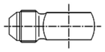
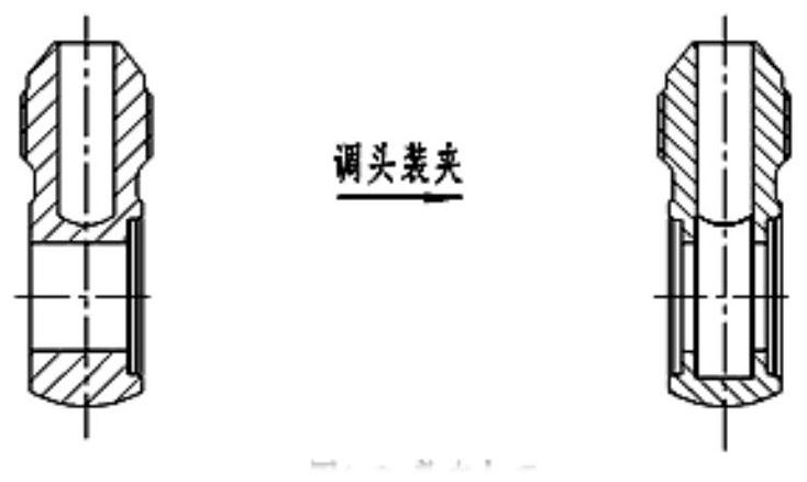
technical field [0001] The invention belongs to the field of fixtures for machining machine tools, in particular to a fixture for numerically controlled lathes for mechanically machining rotary pipe joints with spheres. Background technique [0002] In the processing of rotary pipe joints with spheres, since the sphere part has to be processed with parallel end faces and stepped holes perpendicular to the end faces, there are many processing procedures, especially for titanium alloys, and the single-process processing time is relatively long. The usual process route is as follows: First, the raw material bar such as figure 1 As shown, the thread, cone surface, sphere, and the inner hole of the threaded end are processed by a CNC lathe, and the center needs to be turned and clamped once; and then as shown figure 2 As shown, the milling machine is used for clamping and thread positioning, and the planes on both sides of the spherical end are milled; finally, a hydraulic thre...

Claims


Application Information

Patent Timeline
Patent Type & Authority Applications(China)
IPC IPC(8): B23Q3/12
CPCB23Q3/12
Inventor 张志勇杨盛红杨晓晓
Owner 贵州特冶科技有限公司
Learn More