Robot intelligent grinding and detecting method, terminal equipment and storage medium

A technology of robot intelligence and detection method, which is applied in the direction of instruments, image analysis, image enhancement, etc., can solve the problems of affecting the processing accuracy of workpieces, low processing efficiency, secondary clamping errors, etc., to ensure quality and power performance, and avoid dust and noise pollution, procedures and ease of operation

Active Publication Date: 2020-08-25
HUAZHONG UNIV OF SCI & TECH
View PDF8 Cites 1 Cited by
  • Summary
  • Abstract
  • Description
  • Claims
  • Application Information

AI Technical Summary

Problems solved by technology

The blades in the aero-engine are of various types, large in number and complex in shape, which makes the machining and measurement of the blades very difficult
[0003] At present, most of the blade processing in the blade manufacturing industry at home and abroad is still dominated by manual grinding and polishing. Manual grinding and polishing mainly has the following disadvantages: (1) A large amount of dust and noise will be generated during blade grinding and polishing, which is harmful to the health of workers on the production line. Very unfavorable; (2) Manual grinding and polishing usually determines the grinding and polishing force and grinding and polishing trajectory according to the experience of the workers. It is difficult to guarantee the consistency of the surface of the blades polished by workers with different levels of proficiency, which seriously affects the quality and power of the aero-engine performance; (3) Workers cannot determine whether the size of the workpiece meets the processing requirements in time after grinding and polishing, and need to be sent to the measurement room to be tested by a three-coordinate measuring machine, resulting in complicated procedures and low processing efficiency
The three-coordinate measuring machine has high precision and large measurement range, and is widely used in industrial measurement. It is mainly composed of three-axis precision air-floating platform, contact probe, control system and software. The environmental requirements are high, and it needs to be installed in a clean room with constant temperature and humidity, so it can only be detected by offline measurement
However, the workpiece needs to be disassembled and assembled many times during the off-line measurement process, which is not only inefficient, but also introduces secondary clamping errors, which affects the machining accuracy of the workpiece

Method used


Image

  • Robot intelligent grinding and detecting method, terminal equipment and storage medium
  • Robot intelligent grinding and detecting method, terminal equipment and storage medium
  • Robot intelligent grinding and detecting method, terminal equipment and storage medium

Examples


Embodiment Construction

[0039] In order to make the object, technical solution and advantages of the present invention clearer, the present invention will be further described in detail below in conjunction with the accompanying drawings and embodiments. It should be understood that the specific embodiments described here are only used to explain the present invention, not to limit the present invention. In addition, the technical features involved in the various embodiments of the present invention described below can be combined with each other as long as they do not constitute a conflict with each other.

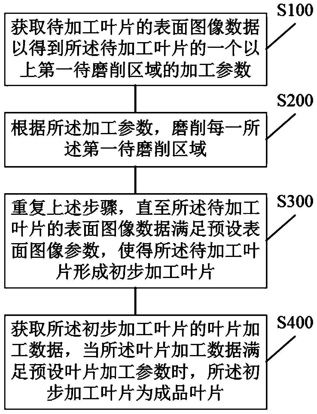
[0040] refer to figure 1 , figure 1 It is a schematic flowchart of the first embodiment of the robot intelligent grinding and detection method of the present invention.

[0041] In the first embodiment, the robot intelligent grinding and detection method includes the following steps:

[0042] S100: Obtain surface image data of the blade to be processed to obtain processing parameters of more ...


PUM


Abstract

The invention discloses a robot intelligent grinding and detecting method, terminal equipment and a storage medium. The method comprises the steps that S100, surface image data of a to-be-machined blade are acquired to obtain machining parameters of one or more first to-be-ground areas of the to-be-machined blade; S200, each first to-be-ground area is ground according to the machining parameters;S300, the steps are repeated until the surface image data of the to-be-machined blade meet preset surface image parameters, so that the to-be-machined blade forms a preliminary machined blade; and S400, blade machining data of the primarily-machined blade are obtained, and when the blade machining data meet preset blade machining parameters, the primarily-machined blade is a finished blade. The self-adaptive closed-loop and unmanned machining of the to-be-machined blade is achieved, the body health of workers is protected, the labor cost is reduced, repeated disassembly and assembly are not needed, the clamping error is small, and the machining precision and the yield are high.

Description

technical field [0001] The invention belongs to the technical field of aeroengine blade grinding, and more specifically relates to a robot intelligent grinding and detection method, a terminal device and a storage medium. Background technique [0002] Aeroengine blades are the core components of aircraft power systems. Aeroengines rely on gas flow to generate thrust. Airflow enters from the air inlet, is compressed by the compressor, burns in the combustion chamber, expands through the turbine to perform work, and is discharged from the exhaust port to perform work in the airflow. During the process, the multi-stage blades in the compressor and turbine provide the main power output of the engine. The blades in aero-engines are of various types, large in number and complex in shape, which makes the machining and measurement of the blades very difficult. [0003] At present, most of the blade processing in the blade manufacturing industry at home and abroad is still dominated...

Claims


Application Information

Patent Timeline
Patent Type & Authority Applications(China)
IPC IPC(8): G06T7/00G06T7/13G06T5/00G06F30/17
CPCG06T7/0004G06T7/13G06T5/003G06F30/17G06F2119/14
Inventor 赵欢姜宗民丁汉
Owner HUAZHONG UNIV OF SCI & TECH
Why Eureka
Try Eureka