
Anti-caking mud cake circulating system for slurry balance shield tunneling machine and shield tunneling machine

A circulation system and mud-water balance technology, which is applied in mining equipment, earthwork drilling, tunnels, etc., can solve the problems of shield machines not being able to excavate normally, project progress delayed and overdue, and enterprise losses, etc., to prevent ground slurry and uplift subsidence accidents, improving safety and reliability, and satisfying the effect of tunneling needs

Pending Publication Date: 2021-02-23
XCMG KAIGONG HEAVY IND NANJING
View PDF0 Cites 0 Cited by
  • Summary
  • Abstract
  • Description
  • Claims
  • Application Information

AI Technical Summary

Problems solved by technology

With the continuous excavation of the shield machine, the entire mud tank is filled and blocked by irregular shapes and different sizes of clay. There is a lot of friction between them, and the heat generated by mutual friction makes the temperature of the cutter head higher and higher, so that the soil in the mud tank and the cutter head is continuously compacted and solidified at high temperature, and finally forms a hard surface in the cutter head and the entire mud tank. The mud cake will cause the torque and thrust to increase continuously, and the excavation speed will decrease. If the mud cake is serious, the shield machine will not be able to excavate normally, and even must be shut down, which will eventually delay the project progress and cause great losses to the enterprise.

Method used


Image

  • Anti-caking mud cake circulating system for slurry balance shield tunneling machine and shield tunneling machine
  • Anti-caking mud cake circulating system for slurry balance shield tunneling machine and shield tunneling machine

Examples


Embodiment Construction

[0019] The present invention will be further described below in conjunction with the accompanying drawings. The following examples are only used to illustrate the technical solution of the present invention more clearly, but not to limit the protection scope of the present invention.

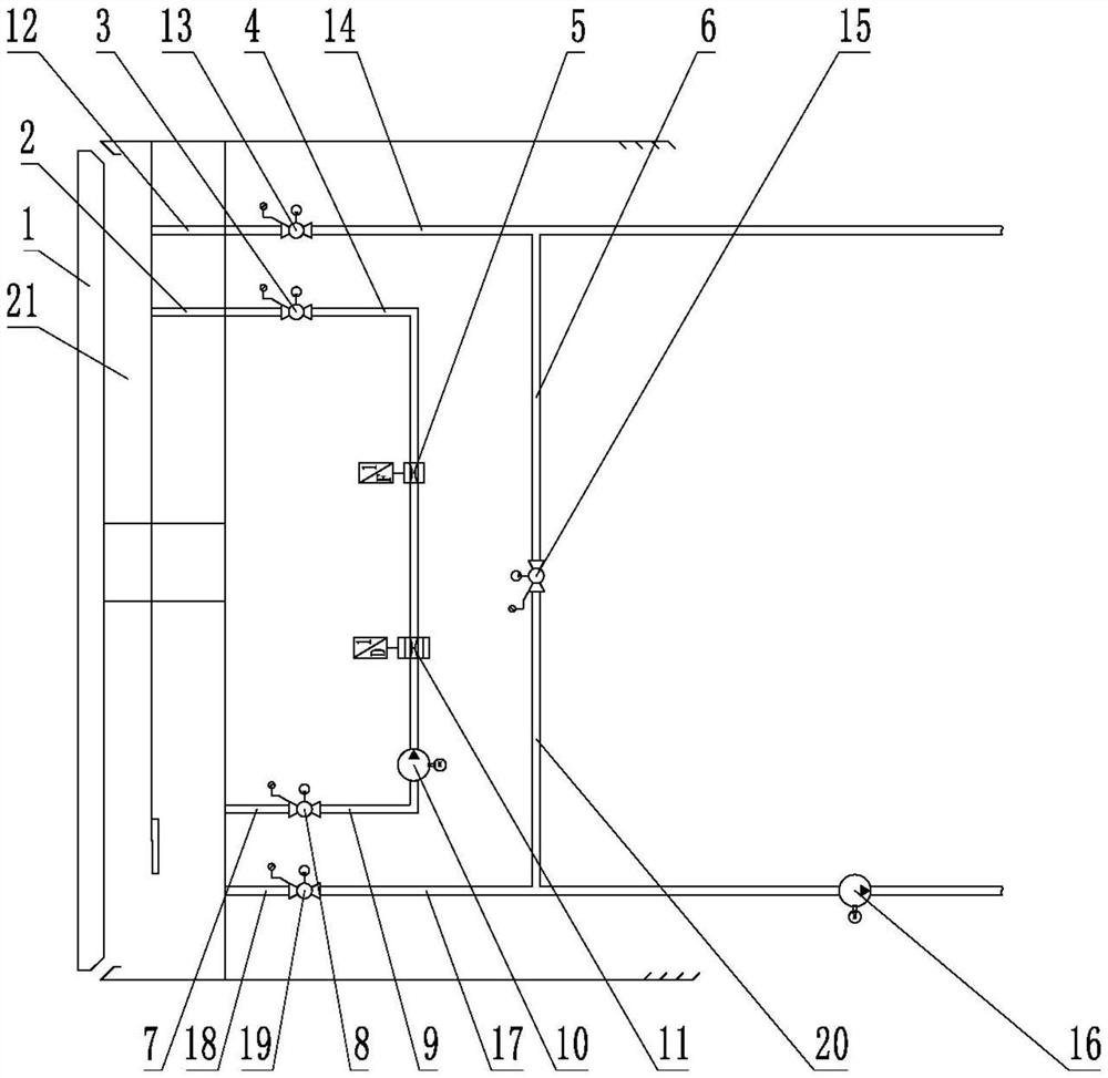
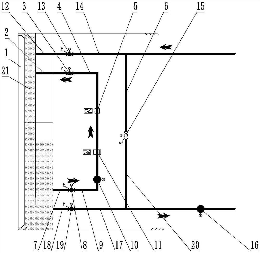
[0020] like figure 1 As shown, an anti-sludge cake circulation system for a mud-water balance shield machine includes a circulating slurry pump 10, a slurry inlet pipe control valve I8, a slurry discharge pipe control valve I3, a slurry inlet circulation pipeline I7, and a slurry inlet circulation Pipeline II9, pulp discharge circulation pipeline I4 and pulp discharge circulation pipeline II2. One end of the slurry feeding circulation pipeline I7 is connected to the opening of the slurry feeding circulation pipe near the bottom of the slurry tank 21, and the other end of the slurry feeding circulation pipeline I7 is connected to one end of the slurry feeding pipe control valve I8, and the slurr...


PUM


Abstract

The invention provides an anti-caking mud cake circulating system for a slurry balance shield tunneling machine and the shield tunneling machine. One end of a slurry inlet circulating pipeline I is connected with a slurry inlet circulating pipe hole near the bottom of a slurry bin, and the other end of the slurry inlet circulating pipeline I is connected with one end of a slurry inlet pipe controlvalve I. The other end of the slurry inlet pipe control valve I is connected with one end of a slurry inlet circulating pipeline II, and the other end of the slurry inlet circulating pipeline II is connected with one end of a circulating slurry pump. The other end of the circulating slurry pump is connected with one end of a slurry discharging circulating pipeline I, and the other end of the slurry discharging circulating pipeline I is connected with one end of a slurry discharging pipe control valve I. The other end of the slurry discharging pipe control valve I is connected with one end ofa slurry discharging circulating pipeline II, the other end of the slurry discharging circulating pipeline II is connected with more than one branch, and the other ends of the branches are connected with a slurry discharging circulating pipe hole near the upper part of a slurry bin. According to the anti-caking mud cake circulating system, the accidents of ground slurry overflowing, upheaval and collapse caused by failure of the mud cake forming cutter head can be effectively prevented, and the safety and reliability of slurry shield construction are improved.

Description

technical field [0001] The invention relates to the technical field of slurry circulation of a mud-water balance shield machine, in particular to an anti-mud cake circulation system for a mud-water balance shield machine and a shield machine. Background technique [0002] At present, there are more and more tunnel projects using mud-water shield machines in China. During the construction of cohesive soil layers, due to the characteristics of high viscosity, difficult flow and small internal friction angle of cohesive soil, the cohesive soil adheres to the cutter head. superior. After the clay cut off by the cutter head enters the mud tank, irregular shapes and different sizes of clay are formed under pressure. First, the center position of the cutter head support is filled and filled, and the opening of the center part is quickly blocked to make the cutter head The soil in the center of the front cannot enter the mud water bin through the opening in the center of the cutter...

Claims


Application Information

Patent Timeline
IPC IPC(8): E21D9/06E21D9/12
CPCE21D9/12E21D9/0642
Inventor 苏延奇徐昊朗李庆龙
Owner XCMG KAIGONG HEAVY IND NANJING
Learn More