Supercharge Your Innovation With Domain-Expert AI Agents!

Sludge plunger pump

A plunger pump, sludge technology, applied in the direction of pumps, pump components, variable capacity pump components, etc., can solve the problems of reducing the service life of hydraulic cylinders, low working efficiency of hydraulic cylinders, limited linear displacement, etc., and achieves low operating resistance. , suitable for large-scale promotion and use, the effect of small power loss

Active Publication Date: 2021-02-23
德润液压科技(常州)有限公司
View PDF5 Cites 1 Cited by
  • Summary
  • Abstract
  • Description
  • Claims
  • Application Information

AI Technical Summary

Problems solved by technology

[0002] The hydraulic cylinder is a linear motion actuator whose output force is proportional to the effective area of ​​the piston and the pressure difference on both sides. Its function is to convert hydraulic energy into mechanical energy. The input of the hydraulic cylinder is the flow and pressure of the fluid, and the output is The speed and force of linear motion, the piston of the hydraulic cylinder can complete the linear reciprocating motion, and the output linear displacement is limited. The hydraulic cylinder is an energy conversion device that converts hydraulic energy into mechanical energy of reciprocating linear motion, so it is used in various fields, but Existing hydraulic cylinders used for sludge treatment are deficient, and the defects are as follows: the hydraulic cylinder has been in sewage for a long time, and its sealing performance is poor, causing impurities in sewage to enter the hydraulic cylinder, which in turn causes damage to the hydraulic cylinder and reduces While reducing the service life of the hydraulic cylinder, it leads to low working efficiency of the hydraulic cylinder

Method used


Image

  • Sludge plunger pump
  • Sludge plunger pump
  • Sludge plunger pump

Examples


Embodiment Construction

[0023] The technical solutions in the embodiments of the present invention will be clearly and completely described below in conjunction with the accompanying drawings in the embodiments of the present invention. Obviously, the described embodiments are only some of the embodiments of the present invention, not all of them. Based on The embodiments of the present invention and all other embodiments obtained by persons of ordinary skill in the art without making creative efforts belong to the protection scope of the present invention.

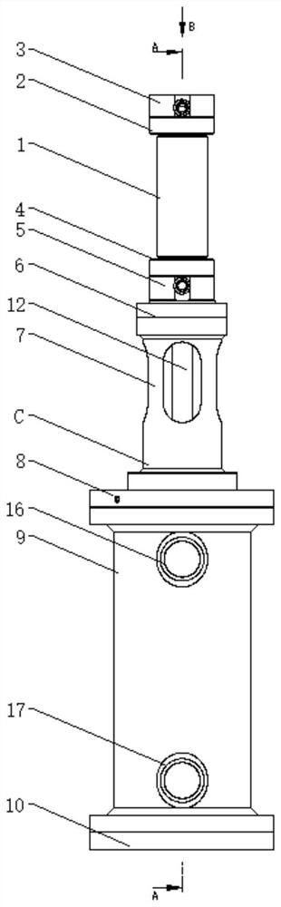
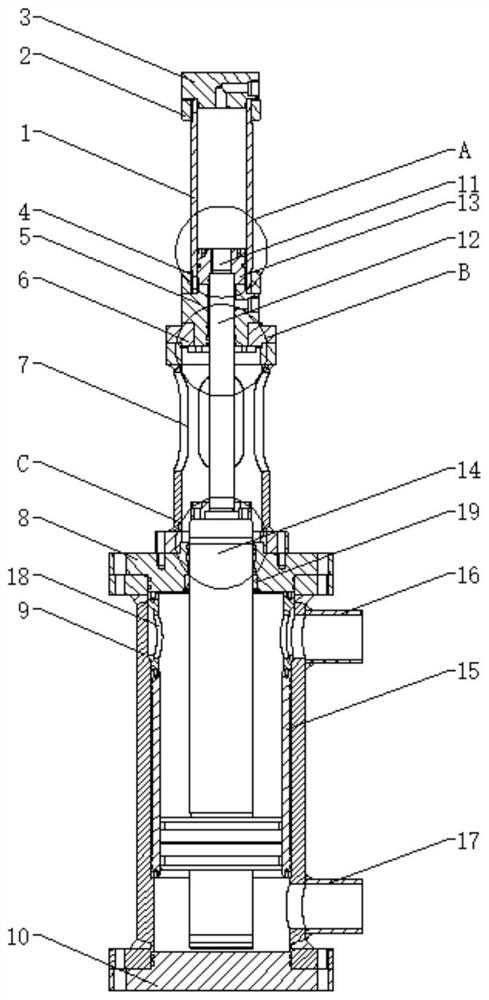
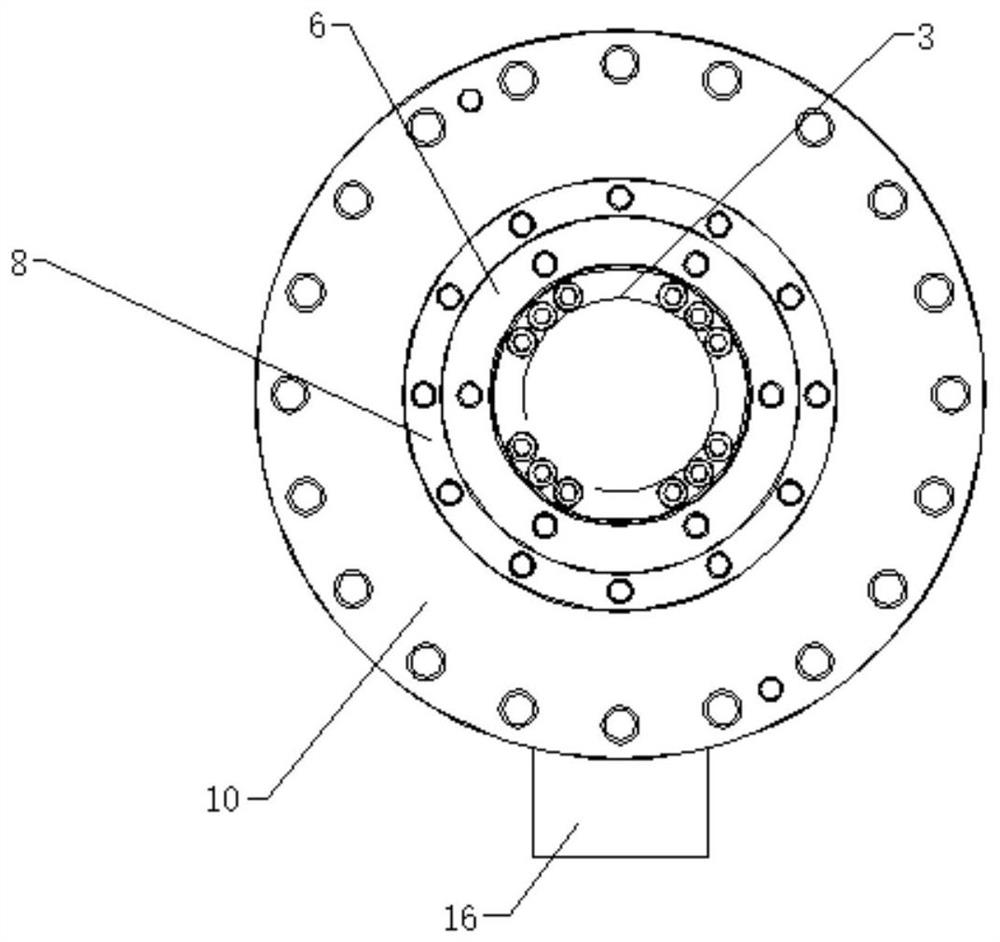
[0024] see Figure 1-6 , the present invention provides a technical solution:

[0025] A sludge plunger pump, including a cylinder 1, the outer wall of the cylinder 1 and the end close to the cylinder 1 is sleeved with an upper flange 2, and the end of the upper flange 2 is connected with a cylinder through a hexagon socket head screw. On the bottom 3, the outer wall of the cylinder 1 and close to the bottom of the cylinder 1 are sleeved with a...


PUM


Abstract

The invention relates to the technical field of sludge plunger pumps, in particular to a sludge plunger pump. The sludge plunger pump comprises a cylinder barrel, wherein an upper flange is connectedto the position, close to the end of the cylinder barrel, of the outer wall of the cylinder barrel in a sleeving mode. According to the sludge plunger pump, one or more sets of different sealing structures are arranged at the connecting positions of all components in a hydraulic cylinder for sealing, so that the layer-by-layer sealing effect is achieved, the problem that the hydraulic cylinder isdamaged due to the fact that impurities in sewage enter the hydraulic cylinder is avoided, the service life of the hydraulic cylinder is guaranteed, the working efficiency of the hydraulic cylinder isguaranteed at the same time, and therefore the hydraulic cylinder is higher in use performance and more suitable for large-range application and popularization; in the using process, a piston rod ofthe hydraulic cylinder is connected with a sludge plunger rod, the piston rod of the hydraulic cylinder moves to drive the sludge plunger rod to reciprocate in a sludge cylinder, sludge can be suckedin and discharged through a one-way valve arranged at an outlet pipe of the sludge cylinder, and compared with a traditional sludge plunger pump, the sludge plunger pump is small in operation resistance and power loss; and the conveying efficiency is higher due to double actions.

Description

technical field [0001] The invention relates to the technical field of sludge plunger pumps, in particular to a sludge plunger pump. Background technique [0002] The hydraulic cylinder is a linear motion actuator whose output force is proportional to the effective area of ​​the piston and the pressure difference on both sides. Its function is to convert hydraulic energy into mechanical energy. The input of the hydraulic cylinder is the flow and pressure of the fluid, and the output is The speed and force of linear motion, the piston of the hydraulic cylinder can complete the linear reciprocating motion, and the output linear displacement is limited. The hydraulic cylinder is an energy conversion device that converts hydraulic energy into mechanical energy of reciprocating linear motion, so it is used in various fields, but Existing hydraulic cylinders used for sludge treatment are deficient, and the defects are as follows: the hydraulic cylinder has been in sewage for a lon...

Claims


Application Information

Patent Timeline
Patent Type & Authority Applications(China)
IPC IPC(8): F04B15/02F04B53/00F04B53/14
CPCF04B15/02F04B53/14F04B53/143F04B53/144F04B53/00
Inventor 朱艺璇朱志闯
Owner 德润液压科技(常州)有限公司
Features
  • R&D
  • Intellectual Property
  • Life Sciences
  • Materials
  • Tech Scout
  • Unparalleled Data Quality
  • Higher Quality Content
  • 60% Fewer Hallucinations
Learn More