
Hydraulic system for shifting gears and changing speeds of headstock sliding gears

A technology of sliding gears and hydraulic systems, which is applied in the field of bedside boxes, can solve the problems of restricting the development of new and old kinetic energy conversion, backwardness, and impossible modification, etc., and achieve the effects of improving market efficiency, reducing costs, and reducing production costs

Inactive Publication Date: 2021-02-23
SHANDONG HUAYU UNIV OF TECH
View PDF0 Cites 0 Cited by
  • Summary
  • Abstract
  • Description
  • Claims
  • Application Information

AI Technical Summary

Problems solved by technology

[0003] The existing CNC machine tool bedside box is driven by a hydraulic cylinder to change gears. It is widely used in the market and various enterprises. It has been used for more than 30 years and has formed a frame. The designer believes that there is no need to modify it, and it is impossible to modify it. Various machine tool manufacturers are still using this old idea and old structure to produce machine tools, which restricts the development requirements for the conversion of new and old kinetic energy, and has fallen behind the times. Therefore, technological innovations have been carried out and a new design idea has been proposed.

Method used


Image

  • Hydraulic system for shifting gears and changing speeds of headstock sliding gears
  • Hydraulic system for shifting gears and changing speeds of headstock sliding gears
  • Hydraulic system for shifting gears and changing speeds of headstock sliding gears

Examples


Embodiment Construction

[0024] The implementation mode of the present invention is illustrated by specific specific examples below, and those who are familiar with this technology can easily understand other advantages and effects of the present invention from the contents disclosed in this description. Obviously, the described embodiments are a part of the present invention. , but not all examples. Based on the embodiments of the present invention, all other embodiments obtained by persons of ordinary skill in the art without making creative efforts belong to the protection scope of the present invention.

[0025] It should be pointed out that the following detailed description is exemplary and is intended to provide further explanation to the present application. Unless defined otherwise, all technical and scientific terms used herein have the same meaning as commonly understood by one of ordinary skill in the art to which this application belongs.

[0026] It should be noted that the terminology ...


PUM


Abstract

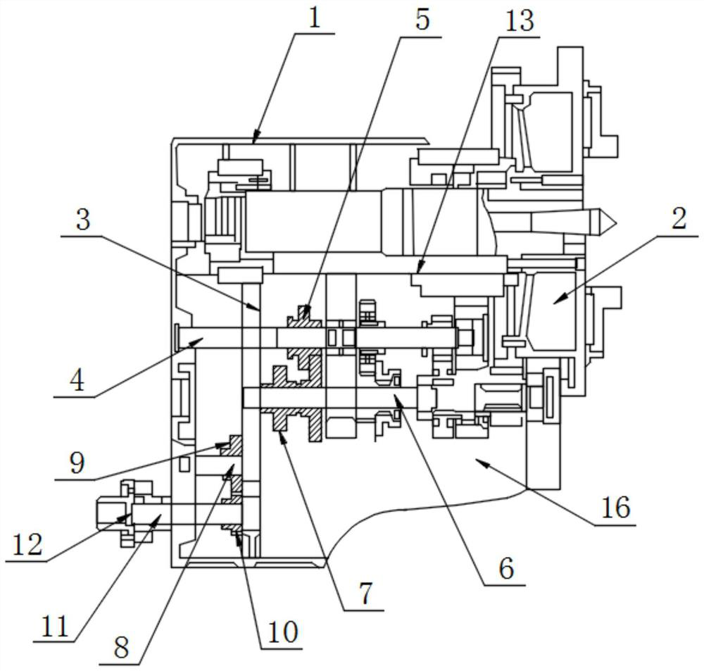
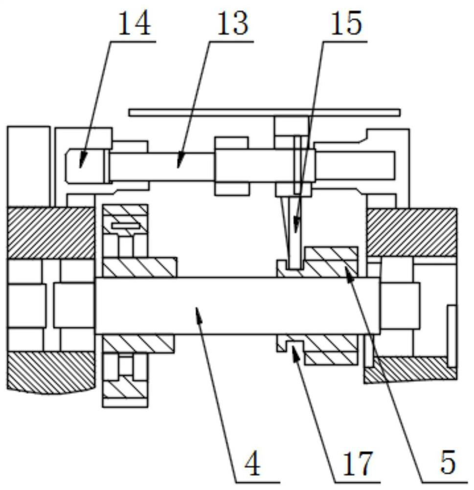
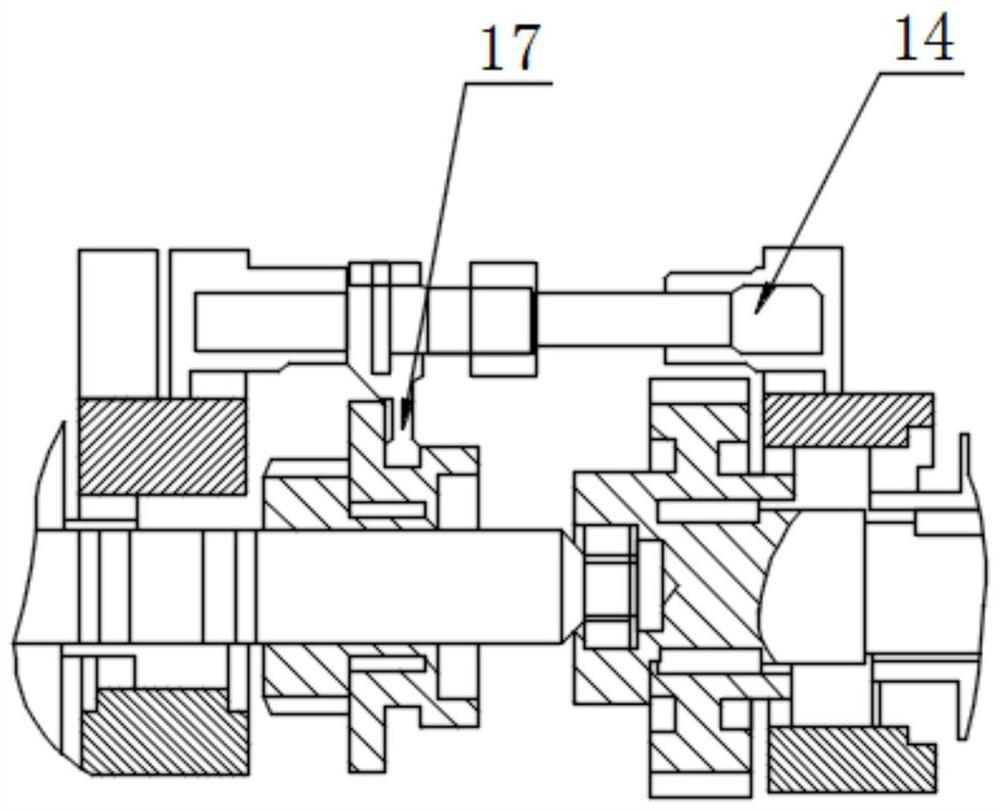
The invention discloses a hydraulic system for shifting gears and changing speeds of headstock sliding gears and belongs to the technical field of headstocks. The hydraulic system comprises a headstock and a gear hydraulic cylinder driving box, wherein the gear hydraulic cylinder driving box is mounted on the inner side of the end of the headstock; an inner cavity is formed in the headstock; and afixing plate is fixedly connected to the inside of the inner cavity; a first rotating shaft is inserted into the fixing plate; and a sliding gear is connected to a position, located on one side of the fixing plate, of the exterior of the first rotating shaft. According to the hydraulic system, a traditional hydraulic control overflow valve, a throttling valve and a hydraulic control one-way valveare not used, the hydraulic system and a lubricating system of the headstock are integrated as a whole; the hydraulic cylinder can move forwards and backwards by only needing two two-position four-way electromagnetic reversing valves; the control method is safe and reliable; hydraulic control gear reversing can be achieved; gears and bearings in the headstock can be lubricated; the manufacturingcost is reduced; and the hydraulic system is suitable for popularization and application.

Description

technical field [0001] The invention relates to the technical field of bedside boxes, in particular to a hydraulic system for shifting gears by sliding gears of the bedside box. Background technique [0002] At present, the existing technologies are CNC lathes, CNC milling machines, vertical machining centers and other machine tools. In order to obtain the main transmission system with high torque and wide speed, there are often one or two pairs of double-sliding gears in the box, which are driven by hydraulic cylinders. Gear shifting and shifting, therefore, require a dedicated set of hydraulic station controls. [0003] The existing CNC machine tool bedside box is driven by a hydraulic cylinder to change gears. It is widely used in the market and various enterprises. It has been used for more than 30 years and has formed a frame. The designer believes that there is no need to modify it, and it is impossible to modify it. Various machine tool manufacturers are still using ...

Claims


Application Information

Patent Timeline
Patent Type & Authority Applications(China)
IPC IPC(8): F15B15/14F15B13/02F16H57/04F16H61/4165B23Q11/12
CPCB23Q11/12F15B13/02F15B15/14F16H57/0467F16H57/0471F16H61/4165
Inventor 谭德宁李永孟凡召陈福德刘耀郑明辉万志远吕静
Owner SHANDONG HUAYU UNIV OF TECH
Learn More