Visual electronic fence and control method thereof

An electronic fence and control method technology, which is applied in the field of substation monitoring, can solve the problems of uneconomical, high cost, and bulky, and achieve the effects of convenient equipment operation and maintenance, improved operation stability, and improved protection capabilities

Pending Publication Date: 2021-02-23
STATE GRID CORP OF CHINA +4
View PDF0 Cites 0 Cited by
  • Summary
  • Abstract
  • Description
  • Claims
  • Application Information

AI Technical Summary

Problems solved by technology

[0004] In response to this problem, although there are many types of safety monitoring devices currently on the market, they are not suitable for on-site safety management and control of substations.
For example, the infrared alarm device on the wall of the substation is not convenient to use at the substati

Method used


Image

  • Visual electronic fence and control method thereof
  • Visual electronic fence and control method thereof
  • Visual electronic fence and control method thereof

Examples


Embodiment 1

[0036] Embodiment 1, this embodiment provides a visual electronic fence;

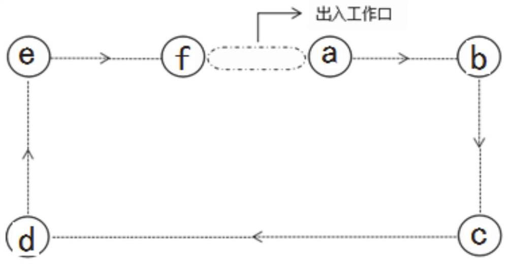
[0037] Such as figure 1 As shown, a visualized electronic fence includes: several electronic fence pillars;

[0038] Number all the electric fence pillars, and form a working area for all the electric fence pillars in the order of numbering from small to large, and there are infrared rays and at least two telescopic belts between adjacent electric fence pillars; among them, The area between the first electric fence pillar and the last electric fence pillar is the entrance and exit, and no telescopic belt is provided for the entrance and exit.

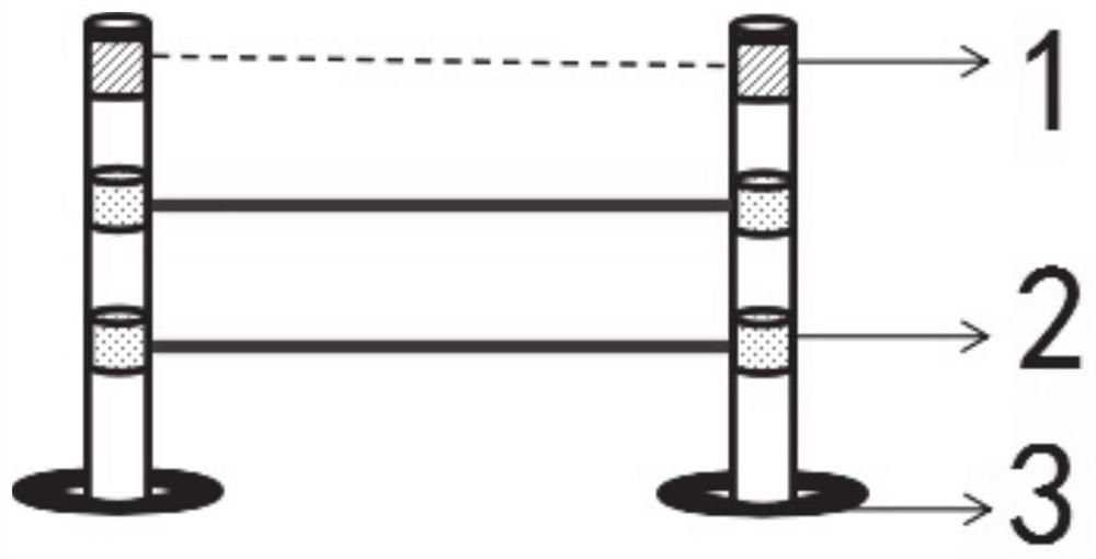
[0039] The installation of two telescopic bands 2 is as follows: figure 2 shown.

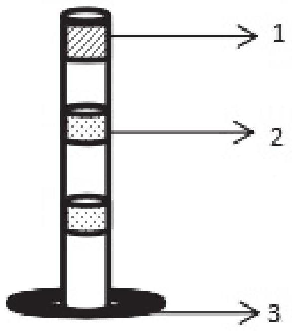
[0040] Further, the electric fence pillars include:

[0041] Support base 3, the support base 3 is fixed on the ground, the support base 3 is fixedly connected to the support bar vertically on the ground, two telescopic belt installation areas are set at intervals on the suppo...

Embodiment 2

[0064] Embodiment 2, this embodiment provides a control method for a visualized electronic fence;

[0065] Such as Figure 6 As shown, a control method for a visualized electronic fence, including:

[0066] S1: Among the two adjacent electric fence pillars, the infrared emitting unit of one electric fence pillar emits infrared rays to the infrared receiving unit of the other electric fence pillar;

[0067] S2: The infrared receiving unit judges whether the optical signal is received, if the optical signal is received, the camera will continue to monitor, the alarm device will not operate, and no alarm information will be sent;

[0068] If no light signal is received, the controller controls the camera to start storing the recorded video; the controller controls the warning light in the alarm device to flash, the controller controls the buzzer in the alarm device to send an alarm signal, and the controller controls the wireless The communication unit sends an alarm signal to ...


PUM


Abstract

The invention discloses a visual electronic fence and a control method thereof. The visual electronic fence comprises a plurality of electronic fence supporting columns. All the electronic fence supporting columns are numbered, a working area for all the electronic fence supporting columns is defined according to the sequence of the numbers from small to large, and infrared rays and at least two telescopic belts are arranged between adjacent electronic fence supporting columns, wherein the area between the first electronic fence supporting column and the last electronic fence supporting columnis an entrance and exit, and the entrance and exit is not provided with a telescopic belt.

Description

technical field [0001] The disclosure relates to the technical field of substation monitoring, in particular to a visualized electronic fence and a control method thereof. Background technique [0002] The statements in this section merely mention background art related to the present disclosure and do not necessarily constitute prior art. [0003] In recent years, with the rapid development of science and technology in our country, the demand for electricity has grown rapidly. Therefore, the safety of substation work occupies an important position in my country's economic development. Among the factors that constitute the safety risk of the substation construction site, the illegal behavior of some personnel on the substation site has become one of the main reasons. [0004] In response to this problem, although there are many types of safety monitoring devices currently on the market, they are not suitable for on-site safety management and control of substations. For ex...

Claims


Application Information

Patent Timeline
IPC IPC(8): G08B13/183G08B7/06G08B25/10H04N7/18H04N5/76E04H17/00E01F13/02
CPCE01F13/028E04H17/00G08B7/06G08B13/183G08B25/10H04N5/76H04N7/18
Inventor 张昭刘洋吕良辉王春罡钟宪成刘海朋张操马顺绪马乐白伟刘生春乔羽樊锁锁省天艳赵学鑫祁宝才赵文强彭洁海景雯徐嘉伟
Owner STATE GRID CORP OF CHINA
Why Eureka
Try Eureka