
Iron plate plasma punching equipment

A punching equipment, plasma technology, applied in the direction of plasma welding equipment, welding equipment, welding equipment, etc., can solve the inconvenience of punching iron plates of different sizes, fixing iron plates, etc.

Pending Publication Date: 2021-02-26
邓子贤
View PDF6 Cites 11 Cited by
  • Summary
  • Abstract
  • Description
  • Claims
  • Application Information

AI Technical Summary

Problems solved by technology

[0004] In order to overcome the shortcomings of the existing technology that it is not convenient to punch holes in iron plates of different sizes and requires workers to manually fix the iron plates, the technical problem of the present invention is: to provide a method that can punch holes in steel plates of different sizes and has a degree of automation Iron plate plasma drilling equipment that is tall and capable of fixing iron plates

Method used


Image

  • Iron plate plasma punching equipment
  • Iron plate plasma punching equipment
  • Iron plate plasma punching equipment

Examples


Embodiment 1

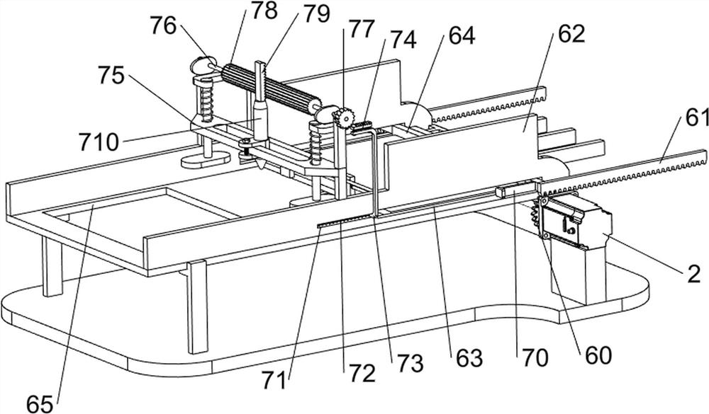
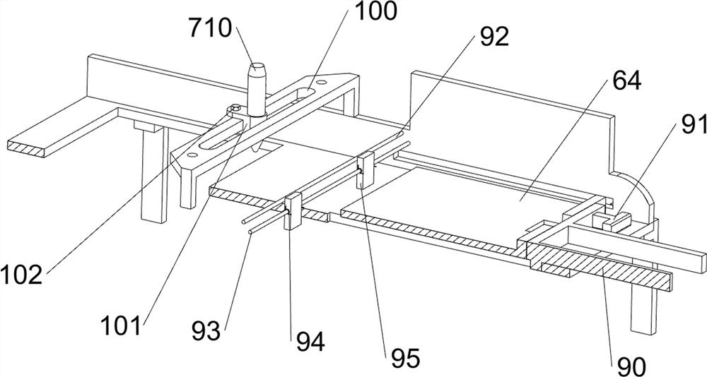
[0026] A kind of iron plate plasma drilling equipment, such as figure 1 with figure 2 As shown, it includes a bottom plate 1, a servo motor 2, a bracket 3, a placement plate 4, a material frame 5, a pushing mechanism 6 and a punching mechanism 7, a servo motor 2 is provided on the top right front side of the bottom plate 1, and multiple A support 3 is provided with a placement plate 4 between the supports 3, the right side of the placement plate 4 top is provided with a material frame 5, the placement plate 4 is provided with a pushing mechanism 6, and the placement plate 4 is provided with a punching mechanism 7.

[0027] When people need to use this equipment, first people place an iron plate in the material frame 5, and then people can start the servo motor 2 and the punching mechanism 7, and the servo motor 2 drives the pushing mechanism 6 to operate, and the pushing mechanism 6 The operation further drives the iron plate to move to the left, and then when the pushing me...

Embodiment 2

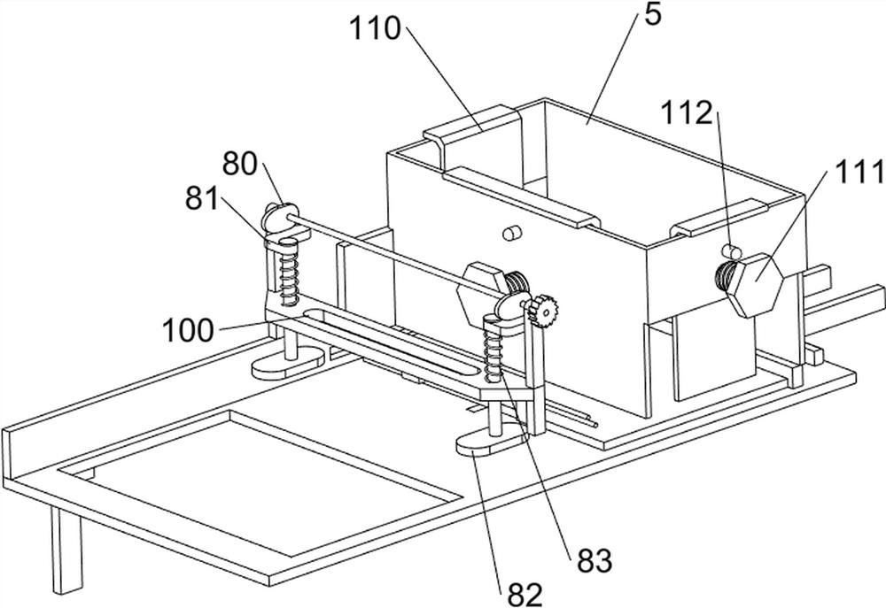
[0033] On the basis of Example 1, such as figure 1 , image 3 with Figure 4 Shown, also comprise hold-down mechanism 8, hold-down mechanism 8 comprises cam 80, special-shaped piece 81, pressing plate 82 and second spring 83, and cam 80 is provided with front and back symmetry on first rotating shaft 76, and front and back symmetry slides on fixed mount 75 Formula is provided with pressing plate 82, and pressing plate 82 tops are all provided with special-shaped block 81, and cam 80 cooperates with special-shaped block 81, and pressing plate 82 is all provided with second spring 83, and second spring 83 is connected with special-shaped block 81 and fixed mount 75.

[0034] When the first rotating shaft 76 rotates, the first rotating shaft 76 drives the cam 80 to rotate, and when the convex part of the cam 80 contacts the special-shaped block 81, the cam 80 squeezes the special-shaped block 81, and then the special-shaped block 81 moves downward, and the special-shaped block 8...


PUM


Abstract

The invention relates to punching equipment, in particular to iron plate plasma punching equipment. The invention provides the iron plate plasma punching equipment which can punch steel plates of different sizes, is high in automation degree and can fix iron plates. The iron plate plasma punching equipment comprises a bottom plate, and a servo motor is arranged on the bottom plate; a plurality ofsupports arranged on the bottom plate; a placing plate arranged between the supports; a material frame arranged on the placing plate; a material pushing mechanism arranged on the placing plate; and apunching mechanism arranged on the placing plate. According to the iron plate plasma punching equipment provided by the invention, leftward conveying of the iron plates is achieved through the material pushing mechanism, then rapid punching of the iron plates is achieved through cooperation of the punching mechanism, and therefore people only need to continuously place the iron plates on the pushing mechanism, and efficient punching can be achieved.

Description

technical field [0001] The invention relates to a punching device, in particular to a plasma punching device for an iron plate. Background technique [0002] For the processing of iron plates, punching is a relatively common method, and it is also a processing method that is widely used. Due to the different uses of iron plates, workers usually need to punch holes in iron plates. First of all, people use iron plates Place it on the workbench, then move the iron plate to the bottom of the punching device, and then people start the punching device to punch holes in the iron plate, which is troublesome to operate like this, and the existing punching device usually has a complicated structure. Most of the punching devices are mostly fixed settings, which are not convenient for punching iron plates of different sizes, and also need workers to manually fix the iron plates when punching holes. [0003] Therefore, in view of the above shortcomings, we need to develop a kind of iron...

Claims


Application Information

Patent Timeline
IPC IPC(8): B23K10/00B23K37/04B23K37/00B23K37/02
CPCB23K10/00B23K37/00B23K37/0252B23K37/0408
Inventor 邓子贤
Owner 邓子贤
Learn More