Multi-angle mounting machine for industrial robot production line machining

An industrial robot and production line technology, applied in metal processing, metal processing equipment, manufacturing tools, etc., can solve problems such as inability to install different models, single-person use of the installation machine, and inability to adjust the overall length of the universal shaft structure. Ensure safe operation and normal use, easy to use effect

Inactive Publication Date: 2021-02-26
合肥酷显智能科技有限公司
View PDF0 Cites 1 Cited by
  • Summary
  • Abstract
  • Description
  • Claims
  • Application Information

AI Technical Summary

Problems solved by technology

[0004] The purpose of the present invention is to provide a multi-angle mounting machine for industrial robot production line processing, to solve the problem that most of the mounting machines on the market proposed in the background technology have fixed rod heads, and cannot change the direction of the front end of the rod head, and cannot test samples at different angles. It is impossible to adjust the overall service length of the universal shaft structure according to site changes, and it is impossible to install different models. The installation machine is only for single use.

Method used


Image

  • Multi-angle mounting machine for industrial robot production line machining
  • Multi-angle mounting machine for industrial robot production line machining
  • Multi-angle mounting machine for industrial robot production line machining

Examples


Embodiment Construction

[0029] The technical solutions in the embodiments of the present invention will be clearly and completely described below in conjunction with the embodiments of the present invention. Apparently, the described embodiments are only some of the embodiments of the present invention, not all of them. Based on the embodiments of the present invention, all other embodiments obtained by persons of ordinary skill in the art without creative efforts fall within the protection scope of the present invention.

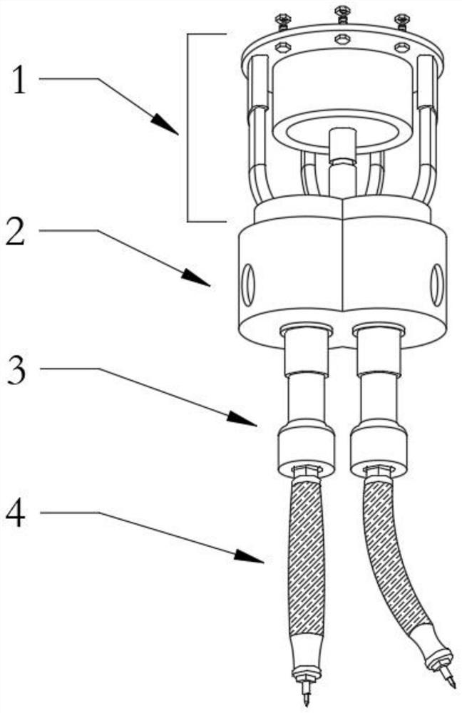
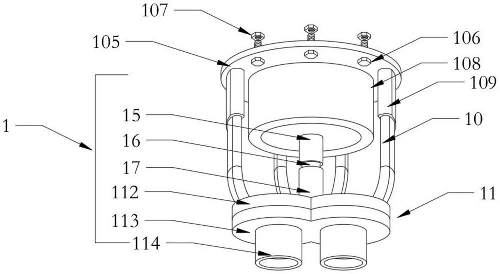
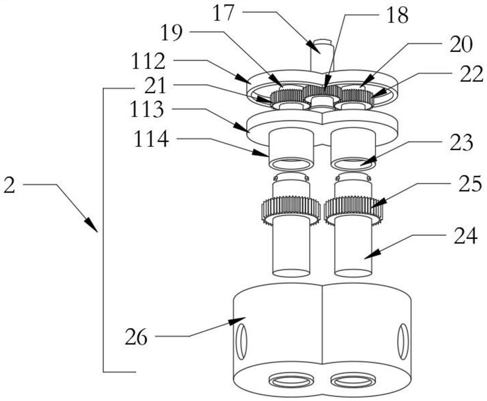
[0030] Such as Figure 1-9 As shown, a multi-angle installation machine for industrial robot production line processing, including a power unit 1, an external sleeve 2, a waist clamping structure 3 and a universal shaft structure 4, the upper part of the power unit 1 is provided with a top plate 105, the top The lower end surface of the disc plate 105 is uniformly provided with several groups of screws 106, the upper end of the top disc plate 105 is provided with nuts 107 correspo...


PUM


Abstract

The invention discloses a multi-angle mounting machine for industrial robot production line machining. The multi-angle mounting machine comprises a power device, an external sleeve, a waist clamping structure and a universal rotating shaft structure, a top disc plate is arranged on the upper portion of the power device, and a plurality of sets of screws are evenly arranged on the surface of the lower end of the top disc plate. Nuts corresponding to the screws are arranged at the upper end of the top disc plate, a motor is fixedly arranged in the middle of the surface of the lower end of the top disc plate, and four sets of inserting groove rods are evenly and fixedly arranged at the positions, close to the edge, of the surface of the lower end of the top disc plate. According to the multi-angle mounting machine, the direction of the front end of a rod head can be changed, within a certain deflection range, the sample screws in different directions and at different angles can be mountedfreely, the overall use length of the universal rotating shaft structure can be adjusted according to specific requirements and site changes, mounting of different machine types is facilitated, handsare protected against injuries caused by the universal rotating shaft structure, the phenomenon of jamming is avoided, and the effective utilization rate of the mounting machine is increased.

Description

technical field [0001] The invention belongs to the technical field of production line processing, in particular to a multi-angle mounting machine for industrial robot production line processing. Background technique [0002] The automatic production line installation machine is an organic combination of the automatic machine system and the automatic production line to realize the integration of automatic processing of products and processes. It is also one of the mainstream directions of today's industrial development. It is formed on the basis of the further development of the continuous assembly line; Its characteristic is that the processing object is automatically transferred from one machine tool to another, and is automatically processed by the installation machine; the task of the worker is only to adjust, supervise and manage the automatic line, and not to participate in direct operation; The beat operation, the production process is highly continuous. [0003] Mos...

Claims


Application Information

Patent Timeline
Patent Type & Authority Applications(China)
IPC IPC(8): B23P19/00
CPCB23P19/00
Inventor 童亮
Owner 合肥酷显智能科技有限公司
Why Eureka
Try Eureka