Wood board cutting device for construction site
A technology for construction sites and cutting devices, which is applied in the direction of manufacturing tools, wood processing appliances, forming/shaping machines, etc., can solve problems such as low efficiency, affect work efficiency, and complicated operation, and achieve the effect of easy cutting
- Summary
- Abstract
- Description
- Claims
- Application Information
AI Technical Summary
Problems solved by technology
Method used
Image

Examples
Embodiment 1
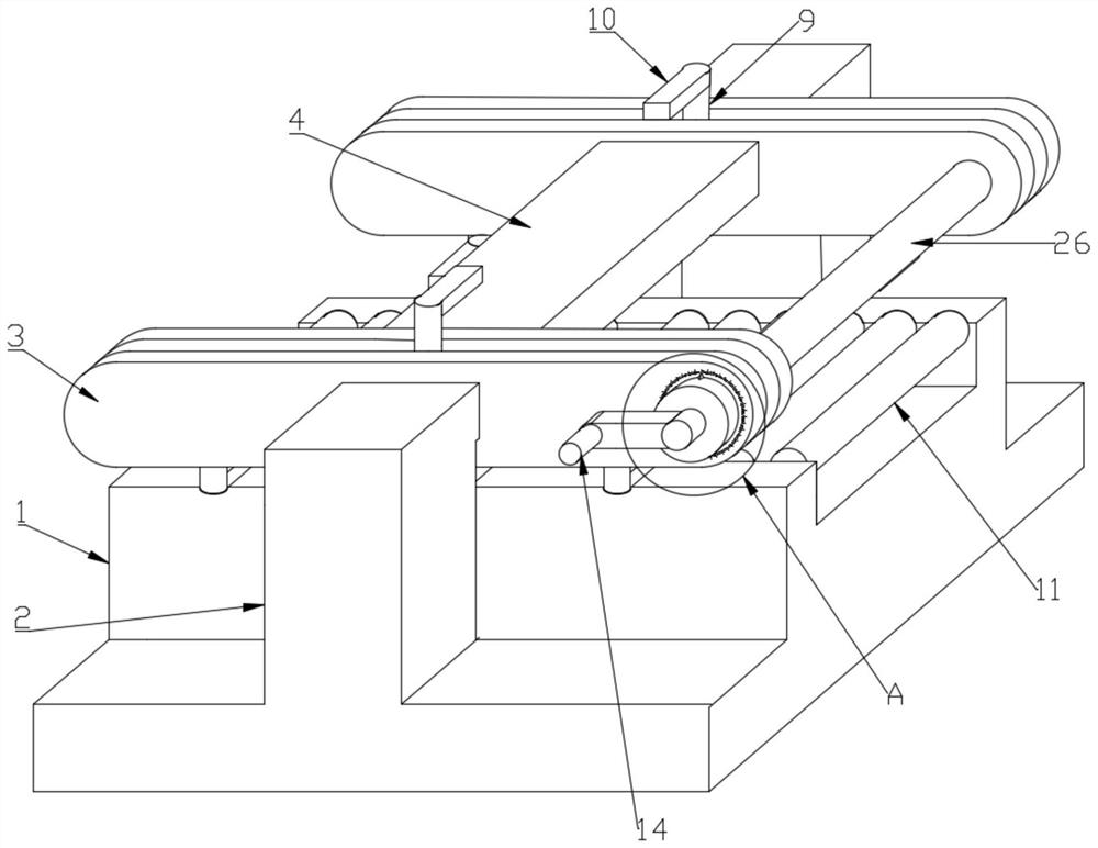
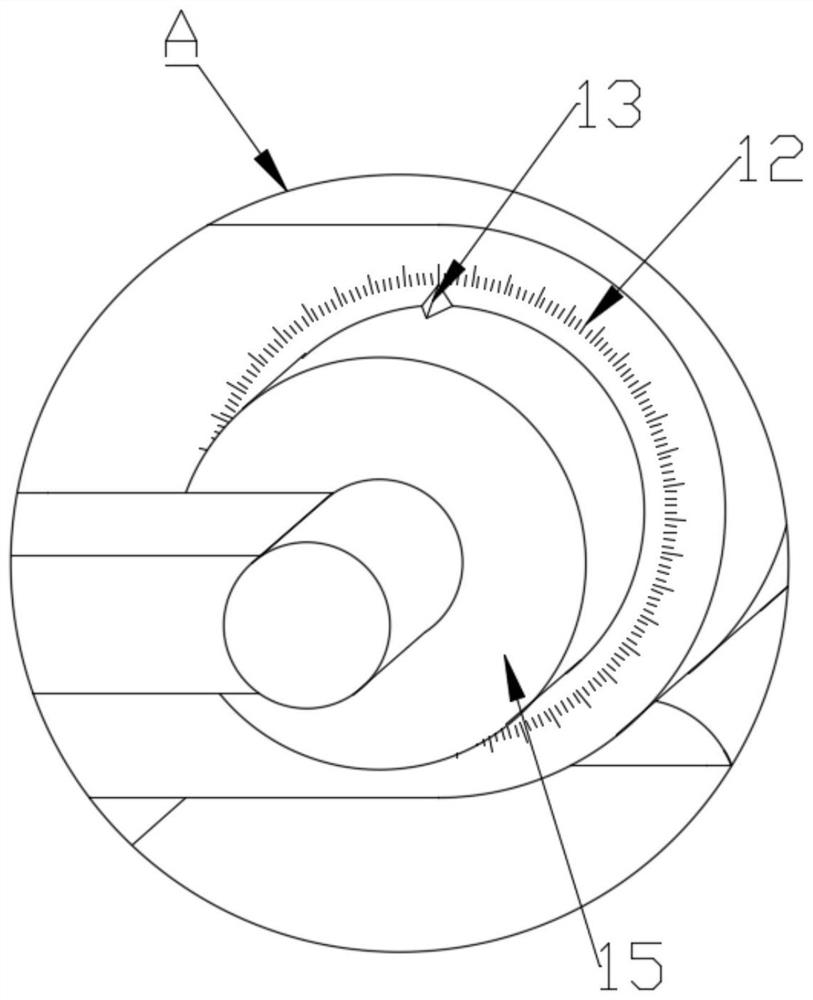
[0025] see Figure 1-5 , this embodiment provides a wood cutting device for a construction site, including a base 1, a connecting frame 4, a cutting blade 16 and two fixing frames 25, two support blocks 2 are symmetrically installed on the base 1, and the two The fixing frames 25 are respectively fixedly installed on the two support blocks 2, and the two fixing frames 25 are fixedly connected through the connecting frame 4, and the cutting blade 16 is installed on the connecting frame 4 through an adjustment mechanism. The frame 25 is made up of a connecting block 6 and two fixing components 3, the connecting block 6 is fixedly installed between the two fixing components 3, and the pushing clamp acting on the plank is installed on the base 1 and the fixing frame 25 mechanism.
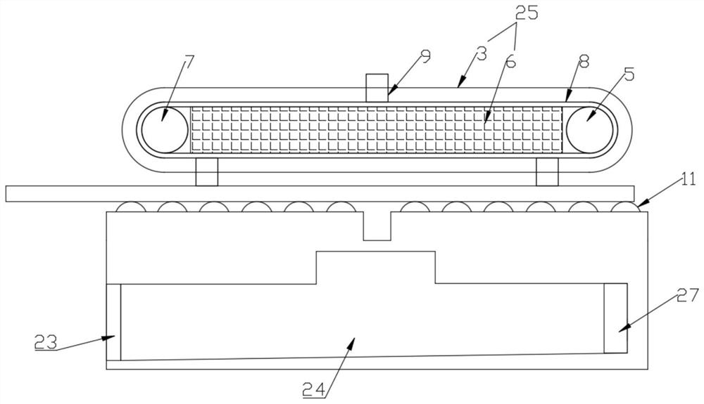
[0026] Described pushing clamping mechanism comprises driving wheel 5, driven wheel 7, clamping part 10 and a plurality of rollers 11, and described driving wheel 5 and driven wheel 7 symmetrical rotat...
Embodiment 2
[0035]A large amount of waste chips will be generated when cutting wood boards, and the waste chips flying randomly will not only easily affect the work efficiency, but also be difficult to clean up. In order to solve this problem, this embodiment is further improved on the basis of embodiment 1. The improvements are as follows: A settling bin 24 is provided in the base 1, the feed port of the settling bin 24 is located below the cutting blade 16, a movable door 23 is installed on the discharge port of the settling bin 24, and a Fan 27 is set up like this, when cutting plank, start fan 27, just can suck in the waste chip that flies in the settling bin 24.
[0036] Further, in order to facilitate the cleaning of the sedimentation bin 24, the following design is carried out. The bottom of the inner cavity of the sedimentation bin 24 is arranged at an inclination, so that the waste debris in the sedimentation bin 24 can be cleaned conveniently.
PUM
 Abstract
Description
Claims
Application Information
PatSnap Eureka turns technology decisions into work you can execute. Powered by our Innovation Knowledge Graph, it runs expert workflows across engineering, life sciences, materials and intellectual property. Get your review-ready output in minutes.


