Soap custom surface engraving machine

A machine and soap technology, applied in the field of soap custom surface engraving machines, can solve the problems of difficult soap fixation, low soap efficiency, and cumbersome process of replacing soap at intervals, so as to improve the engraving efficiency and reduce labor intensity.

Pending Publication Date: 2021-02-26
张驰
View PDF0 Cites 1 Cited by
  • Summary
  • Abstract
  • Description
  • Claims
  • Application Information

AI Technical Summary

Problems solved by technology

[0004] In order to overcome the low efficiency of manual carving of soap by workers, and the complicated process of replacing soap at intervals, because the nature of soap itself is relatively slippery, it is difficult for workers to fix the soap by hand. The technical problem to be solved is: to provide a Carving soap, which can realize automatic replacement of soap at intervals, can clamp and fix soap at the same time, can screen soap, and can shake off soap powder from soap. Soap custom surface engraving machine

Method used


Image

  • Soap custom surface engraving machine
  • Soap custom surface engraving machine
  • Soap custom surface engraving machine

Examples


Embodiment 1

[0075] A soap custom surface engraving machine such as figure 1 As shown, it includes a base 1, a printing mechanism 2 and a material receiving mechanism 3. The printing mechanism 2 is welded on the front side of the top of the base 1, and the material receiving mechanism 3 is installed on the rear side of the top of the base 1. The material receiving mechanism 3 cooperates with the printing mechanism 2.

[0076] When the worker needs to carve the soap, the worker needs to place the soap on the material receiving mechanism 3 first. After the worker places the soap on the material receiving mechanism 3, the worker needs to start the printing mechanism 2 to expand and contract. When the printing mechanism 2 stretches , the printing mechanism 2 will drive the material receiving mechanism 3 to move forward. When the material receiving mechanism 3 moves to the front side and is located under the printing mechanism 2, the printing mechanism 2 can engrave the soap. When the printing m...

Embodiment 2

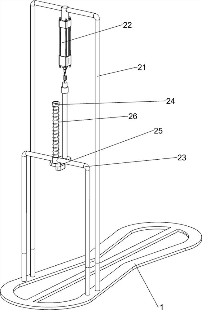
[0078] In a preferred embodiment of the present invention, as figure 2 As shown, the printing mechanism 2 includes a first support rod 21, a cylinder 22, a first fixed sliding sleeve 23, a first connecting rod 24, a pressing knife 25 and a first spring 26, and the front side of the top of the base 1 is fixedly connected with a first support Rod 21, the top of the first support rod 21 is fixedly connected with the cylinder 22 by bolts, the front side of the base 1 is fixedly connected with the first fixed sliding sleeve 23, the first fixed sliding sleeve 23 is located at the front side of the first support rod 21, the first fixed sliding sleeve Slip type is provided with first connecting rod 24 in cover 23, and first connecting rod 24 tops are connected with cylinder 22 telescoping rod bottom ends, and first connecting rod 24 bottoms are equipped with pressing knife 25, and the first connecting rod 24 is sleeved with the first A spring 26 , the two ends of the first spring 26 ...

Embodiment 3

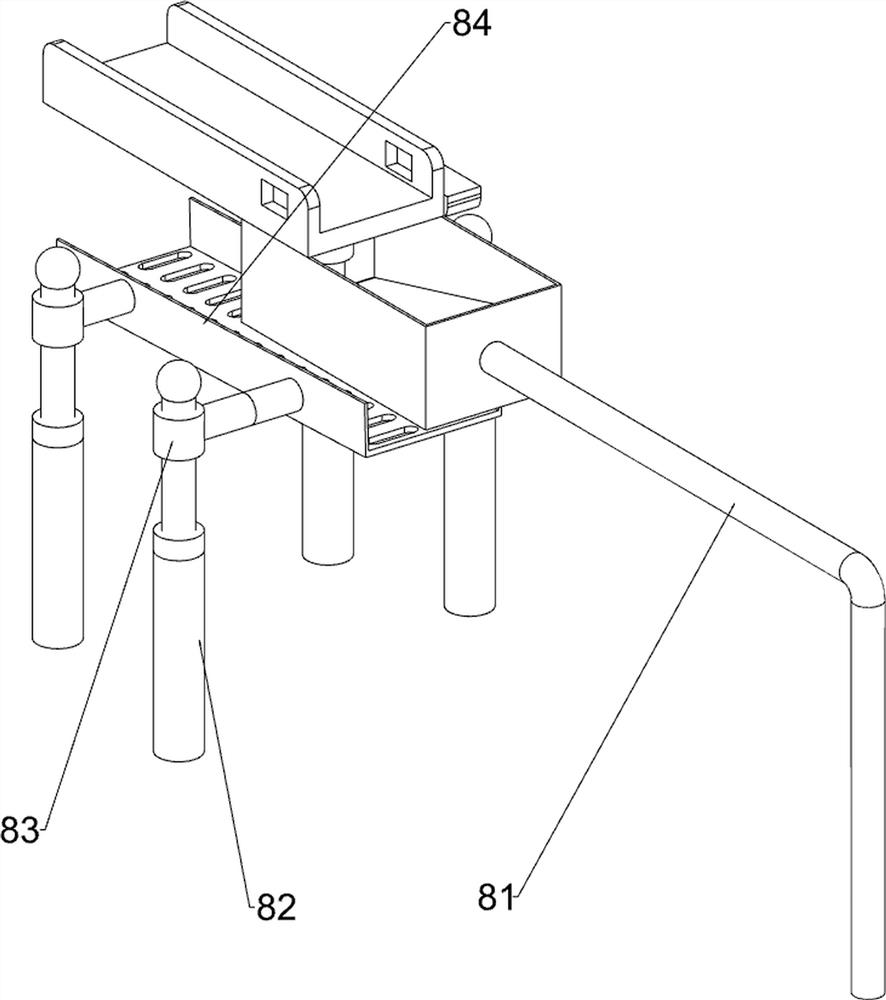
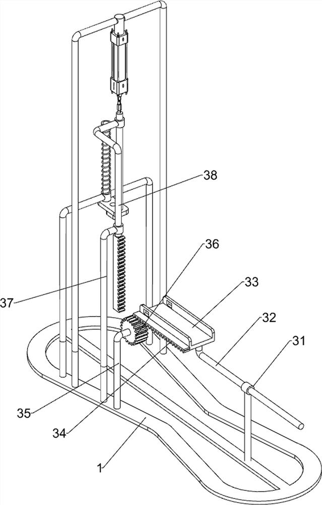
[0081] In a preferred embodiment of the present invention, as figure 1 and Figure 3-Figure 10 As shown, the material receiving mechanism 3 includes a first sliding sleeve 31, a first sliding rod 32, a material receiving working plate 33, a first rack 34, a second support rod 35, a first spur gear 36, a second fixed sliding sleeve 37 and the rack bar 38, the base 1 rear side is fixedly connected with the first sliding sleeve 31, the first sliding sleeve 31 is slidingly provided with the first sliding rod 32, and the top of the front end of the first sliding rod 32 is equipped with a material receiving work plate 33 , the material receiving work plate 33 is in contact with the pressing knife 25, the right side of the material receiving work plate 33 is welded with the first rack 34, the right side of the top of the base 1 is fixedly connected with the second support rod 35, and the second support rod 35 top is The end rotation type is provided with a first straight gear 36, th...


PUM


Abstract

The invention relates to an engraving device, in particular to a soap custom surface engraving machine. Through the soap custom surface engraving machine, soaps can be engraved, automatically replacedat intervals, clamped and fixed and screened, and soapsuds can be shaken off the soaps. The soap custom surface engraving machine comprises a base and a printing mechanism, and the printing mechanismis welded to the top of the base. According to the soap custom surface engraving machine, the printing mechanism is arranged and is matched with a receiving mechanism, so that soap engraving work canbe realized; a clamping mechanism is matched with the printing mechanism, so that the soaps can be clamped, and the engraving efficiency is effectively improved; and a discharging mechanism is matched with a storage mechanism, so that the soaps can be conveyed to a receiving working plate at intervals, and the labor intensity of workers is effectively lowered.

Description

technical field [0001] The invention relates to an engraver, in particular to a soap custom-made surface engraving machine. Background technique [0002] In order to increase the publicity of soap in most soap factories, workers in soap factories usually carve custom patterns on the surface of soap. Existing soap factories generally use manual carving by workers. The efficiency of manual carving of soap by workers is low, and workers are replaced at intervals. The process of soaping is more cumbersome, because the nature of soap itself is relatively slippery, it is difficult for workers to fix the soap by hand. [0003] Therefore, for above-mentioned prior art problem, we have designed a kind of soap that can be carved, can realize automatic interval replacement soap, can clamp and fix soap at the same time, and can screen soap, and can remove soap powder from soap Shake off soap on custom surface engraving machines. Contents of the invention [0004] In order to overcom...

Claims


Application Information

Patent Timeline
Patent Type & Authority Applications(China)
IPC IPC(8): B44B5/00B44B5/02B08B7/02B08B13/00C11D13/00C11D13/22C11D17/00
CPCB08B7/02B08B13/00B44B5/0019B44B5/0052B44B5/02B44B5/022B44B5/024B44B2700/12C11D13/00C11D13/22C11D17/00
Inventor 张驰
Owner 张驰
Why Eureka
Try Eureka