Printing and dyeing airing device

A technology of drying device and drying rod, which is applied in the direction of processing textile material equipment configuration, liquid/gas/steam removal by air jet method, and processing textile material carrier, etc., which can solve the problem that printing and dyeing and drying cannot be carried out at the same time, and the drying rack for printing and dyeing is inconvenient to adjust , Poor stability of drying racks, etc., to reduce the printing and dyeing procedures, increase optional types, and improve efficiency

Pending Publication Date: 2021-02-26
懂效岩
View PDF1 Cites 1 Cited by
  • Summary
  • Abstract
  • Description
  • Claims
  • Application Information

AI Technical Summary

Problems solved by technology

[0003] Chinese invention CN108396488A discloses an easy-to-adjust drying rack for printing and dyeing. motor, the output end of each forward and reverse motor is fixedly connected with a bobbin, the inner top wall of each cavity is provided with a first through hole, and the upper surface of the bottom plate is fixedly connected with two symmetrical fixed rods, each fixed There are first grooves on the bottom surface of the rods, which can effectively adjust the height of the support rods, realize the adjustment of the height of the drying rods, and solve the problem that the existing drying racks for printing and dyeing are not easy to adjust
[0004] However, the existing drying racks for printing and dyeing directly drive the drying rod up and down through the driving mechanism. When the drying rod is driven to start lifting, it is easy to shake, the stability of the drying rack is relatively poor, and the environment for printing and dyeing is poor. The material is easy to adhere to the drying cloth again to cause pollution, and it is impossible to effectively remove the floating matter attached to the device to avoid clogging. The height of the drying rack is high, and it is impossible to remove the cloth on the drying rack easily. Restrictions, the cloth that can be printed and dyed at one time is limited, the efficiency of printing and dyeing is low, and it is impossible to print, dye and dry at the same time

Method used


Image

  • Printing and dyeing airing device
  • Printing and dyeing airing device
  • Printing and dyeing airing device

Examples


Embodiment 1

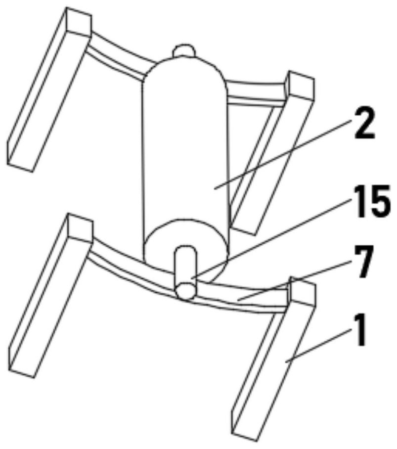
[0033] see Figure 1-3, the present invention provides a technical solution: a printing and dyeing drying device, including a mounting frame 1, characterized in that: the mounting frame 1 is symmetrically installed, a drying rod 2 is installed between the mounting frames 1, and the mounting frame 1 includes a fixed rod 3 and A The top of the type bar 4 and the A-type bar 4 is provided with a guide groove 5, and a guide roller 6 is rotatably connected between the two sides of the inner wall of the guide groove 5, and the side of the fixed bar 3 close to the A-type bar 4 is fixedly connected with a support bar 7, Support bar 7 is slidingly connected with guide roller 6, and one side of drying rod 2 is provided with drainage groove 10, and drainage groove 10 runs through drying rod 2, and the outer side of drying rod 2 is evenly provided with ventilating hole 11, and both ends of drainage groove 10 are installed Drainage device 12 is arranged.

[0034] The drainage device 12 inc...

Embodiment 2

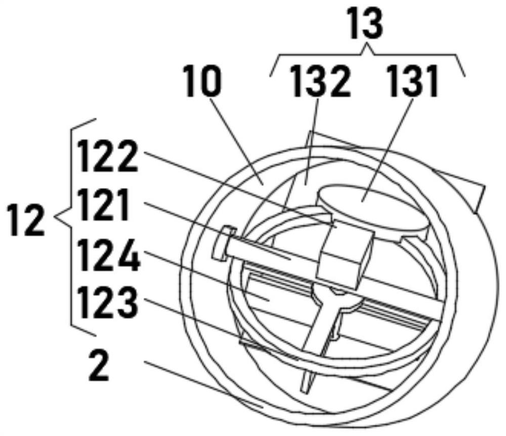
[0039] see Figure 1-3 , the present invention provides a technical solution: on the basis of Embodiment 1, a thrust reverser 13 is installed inside the drainage tank 10 close to the drainage device 12, and the thrust reverser 13 includes a counterweight 131, and the counterweight 131 is installed On the top of the drainage frame 123 , the installation frame 121 is rotatably connected with the inner wall of the drainage groove 10 , and the tops of both ends of the drainage groove 10 are fixedly connected with inclined screen plates 132 .

[0040] During use, due to the gravitational effect of the counterweight 131, the drainage frame 123 and the drainage fan blade 124 are driven to rotate until the counterweight 131 and the drainage motor 122 are respectively located on both sides of the mounting frame 121, so that the drainage frame 123 and the drainage fan blade 124 are rotated again. Stable, the air moves upward to the mobile phase drainage fan blade 124, the flocs in the a...

Embodiment 3

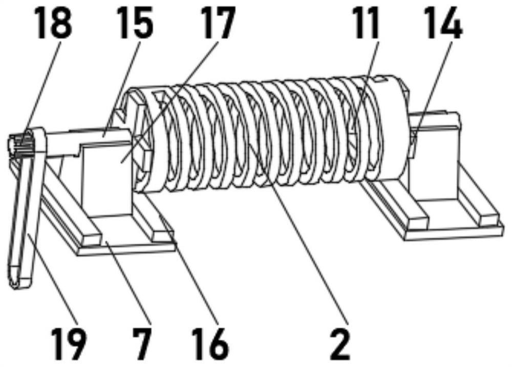
[0042] see Figure 1-5 , the present invention provides a technical solution: on the basis of Embodiment 1, a lifting motor 8 is installed on one side of the A-shaped bar 4, and the output end of the lifting motor 8 is connected to the support bar 7 through a connecting rope 9, and the support bar 7 The limit bar 16 is installed symmetrically on the top, the top of the support bar 7 is slidably connected with the guide frame 17 between the two sides of the limit bar 16, and the top of the rotating rod 15 is rotatably connected with the guide frame 17.

[0043] One end of the rotating rod 15 is fixedly connected with a gear rod 18 , and the outer side of the gear rod 18 is sheathed with a gear chain 19 , and the gear chain 19 meshes with the gear rod 18 .

[0044] During use, put the rotating rod 15 at both ends of the drying rod 2 on the support bar 7, start the lifting motor 8, and the lifting motor 8 pulls the support bar 7 through the connecting rope 9 to move in the direct...


PUM


Abstract

The invention discloses a printing and dyeing airing device, and relates to the technical field of printing and dyeing equipment. The printing and dyeing airing device comprises mounting frames, the mounting frames are symmetrically mounted, and an airing rod is mounted between the mounting frames. Each mounting frame comprises a fixing rod and an A-shaped rod, guide grooves are formed in the topsof the A-shaped rods, guide rollers are rotatably connected between the two sides of the inner walls of the guide grooves, supporting strips are fixedly connected to the sides, close to the A-shapedrods, of the fixing rods, and the supporting strips are slidably connected with the guide rollers. According to the printing and dyeing airing device, shaking generated when the airing rod ascends anddescends can be avoided, the stability of the airing rod is improved, the airing environment is purified, flocculent floating objects in air are removed, the situation that the flocculent floating objects in the air are prone to adhering to aired cloth again to cause pollution is avoided, the quality of the printed and dyed cloth is improved, the floating objects adsorbed on the airing rod can beremoved, the situation that the floating objects block the airing rod and affect the purification function is avoided, and cloth on an airing frame can be conveniently taken down.

Description

technical field [0001] The invention relates to the technical field of printing and dyeing equipment, in particular to a printing and dyeing drying device. Background technique [0002] Printing and dyeing is a combination of physical and chemical treatment of textiles, such as adding patterns and patterns to textiles, changing the color of textiles and related pre-treatment processes, etc., through physical or chemical changes between dyes and fibers , will make the textile have a certain color and gloss. According to the different printing and dyeing objects, the printing and dyeing process can be divided into cotton textile printing and dyeing, linen textile printing and dyeing, wool textile dyeing and finishing, silk printing and dyeing, etc. With the continuous improvement of dyeing technology With the development and development, the colors of textiles dyed in ancient my country are also constantly enriched. In the printing and dyeing process, drying racks are used to dr...

Claims


Application Information

Patent Timeline
Patent Type & Authority Applications(China)
IPC IPC(8): D06B15/00D06B15/09D06B23/04D06B3/10D06B23/20
CPCD06B3/10D06B15/00D06B15/09D06B23/04D06B23/20
Inventor 懂效岩
Owner 懂效岩
Why Eureka
Try Eureka