Fireproof building steel beam connecting device convenient to install

A connection device and a technology for fire-proof buildings, which are applied in the field of building steel beams, can solve problems such as increased use costs, accidents, and easy corrosion, and achieve the effects of reducing the incidence of accidents, preventing changes in strength, and avoiding positioning

Inactive Publication Date: 2021-02-26
福州市连江县利凯科技有限公司
View PDF0 Cites 0 Cited by
  • Summary
  • Abstract
  • Description
  • Claims
  • Application Information

AI Technical Summary

Problems solved by technology

[0002] Steel structure building is a new type of building system. Compared with traditional concrete buildings, steel structure buildings have higher strength and earthquake resistance. Steel materials can be reused, reducing construction waste, and are more environmentally friendly. However, buildings There is an obvious defect in steel beam structure buildings, which are not fire-resistant and easy to corrode. The traditional treatment method is to apply anti-corrosion and fire-proof coatings on the surface, which greatly increases the cost of use. At the same time, manual positioning is required during the installation of building steel beams. and fixing, it is easy to cause accidents, a fire-proof building steel beam connection device that is easy to install set forth in the present invention can solve the above problems

Method used


Image

  • Fireproof building steel beam connecting device convenient to install
  • Fireproof building steel beam connecting device convenient to install
  • Fireproof building steel beam connecting device convenient to install

Examples


Embodiment Construction

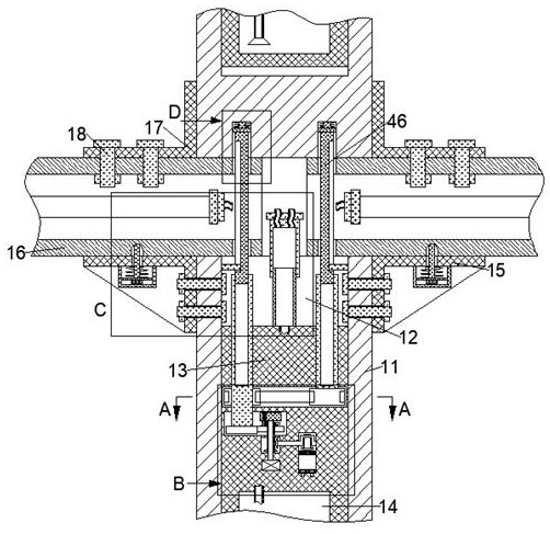
[0019] Combine below Figure 1-5 The present invention is described in detail, wherein, for the convenience of description, the orientations mentioned below are defined as follows: figure 1 The up, down, left, right, front and back directions of the projection relationship itself are the same.

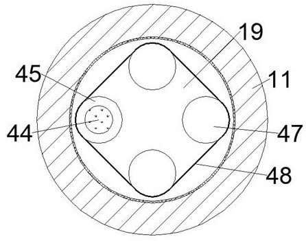
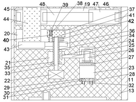
[0020] An easy-to-install fireproof building steel girder connection device according to the present invention includes a vertical steel beam 11, the upper end of the vertical steel beam 11 is provided with a storage cavity 12 with an opening upward, and the inner wall surface of the lower side of the storage cavity 12 is fixed. A limiting body 13 is provided, and a cooling liquid storage cavity 14 capable of storing cooling liquid is provided in the limiting body 13. The upper left and right end faces of the vertical steel beam 11 are fixed with mutually symmetrical upper side tripods 15. The upper end surface of the upper side tripod 15 is flush with the upper end surface of the ver...


PUM


Abstract

The invention discloses a fireproof building steel beam connecting device convenient to install. The fireproof building steel beam connecting device comprises a vertical steel beam, wherein a storagecavity with an upward opening is formed in the upper end face of the vertical steel beam; a limiting machine body is fixedly arranged on the inner wall face of the lower side of the storage cavity; acooling liquid storage cavity capable of storing cooling liquid is formed in the limiting machine body; and upper side triangular frames which are symmetrical to each other are fixedly arranged on theleft end face and the right end face of the upper side of the vertical steel beam. According to the fireproof building steel beam connecting device, positioning holes are utilized, so that rapid installation and positioning of a building transverse steel beam are realized, pre-fixing treatment of the steel beam can be realized, the situation that a constructor manually drags the steel beam for positioning is avoided, and the occurrence rate of accidents is effectively reduced; and meanwhile, the cooling liquid is stored in the vertical steel beam, the driving of a motor is controlled throughthe change of the external temperature, so that the steel beam in the high altitude is rapidly cooled, the strength change of the steel beam caused by high temperature is effectively prevented, and meanwhile, deformation and collapse of the building steel beam can be avoided.

Description

technical field [0001] The invention relates to the field of building steel beams, in particular to an easy-to-install fireproof building steel beam connecting device. Background technique [0002] Steel structure building is a new type of building system. Compared with traditional concrete buildings, steel structure buildings have higher strength and earthquake resistance. Steel materials can be reused, reducing construction waste, and are more environmentally friendly. However, buildings There is an obvious defect in steel beam structure buildings, which are not fire-resistant and easy to corrode. The traditional treatment method is to apply anti-corrosion and fire-proof coatings on the surface, which greatly increases the cost of use. At the same time, manual positioning is required during the installation of building steel beams. And fixed, it is easy to cause accidents, a fire-proof building steel beam connection device that is easy to install explained in the present i...

Claims


Application Information

Patent Timeline
IPC IPC(8): E04B1/24E04B1/58E04B1/62E04B1/94
CPCE04B1/24E04B1/2403E04B1/58E04B1/62E04B1/94E04B2001/2415E04B2001/2457E04B2001/949
Inventor 徐夏丽
Owner 福州市连江县利凯科技有限公司
Why Eureka
Try Eureka