A miniature shaft type roller drive mechanism

A driving mechanism and micro-shaft technology, applied in the direction of electric components, transmission devices, electromechanical devices, etc., can solve the problems of low precision and large volume, and achieve the effect of high rotation precision of rollers, precise control of rotation and stop angles, and simple assembly.

Active Publication Date: 2022-05-24
中机试验装备股份有限公司
View PDF0 Cites 0 Cited by
  • Summary
  • Abstract
  • Description
  • Claims
  • Application Information

AI Technical Summary

Problems solved by technology

[0005] The invention designs and develops a miniature shaft roller driving mechanism, through the cooperation of the driving motor and the rotating mechanism, it overcomes the problems of large volume and low precision of the traditional tooling drive

Method used


Image

  • A miniature shaft type roller drive mechanism
  • A miniature shaft type roller drive mechanism
  • A miniature shaft type roller drive mechanism

Examples


Embodiment Construction

[0044] The present invention will be further described in detail below with reference to the accompanying drawings, so that those skilled in the art can implement it with reference to the description.

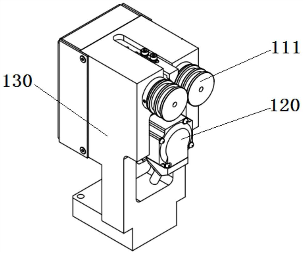
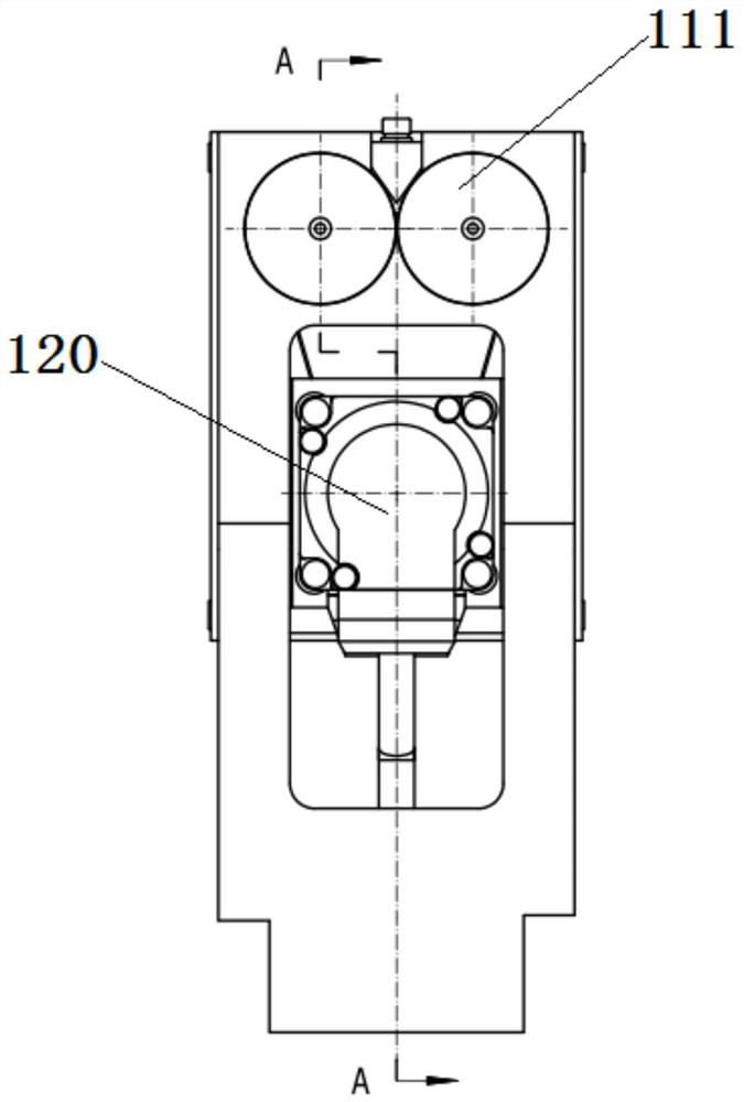
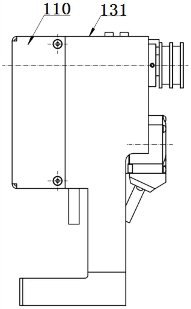
[0045] like Figure 1-7 As shown, the present invention provides a miniature shaft-type roller drive mechanism, including: a main shaft 110 , a second pulley 111 , a first locking nut 112 , a first bearing 113 , a sleeve 114 , a first bushing 115 , and a key 116 , the second bushing 117 , the second locking nut 118 , the second bearing 119 , the first pulley 121 of the drive motor 120 , the conveyor belt 122 , and the bracket 130 .

[0046] like figure 1 , Figure 5 As shown, the driving motor 120 is supported and arranged in the middle of the bracket 130, the first pulley 121 is connected to the output end of the driving motor 120, the two rotating mechanisms are symmetrically arranged, and one end of the rotating mechanism passes through and is rotatably supported on the up...


PUM


Abstract

The invention discloses a miniature shaft roller driving mechanism, which comprises: a bracket; a driving motor, which is supported and arranged in the middle of the bracket; a first pulley, which is connected to the output end of the driving motor; two rotating mechanisms, It is arranged symmetrically, one end of the rotating mechanism passes through and is rotatably supported on the upper part of the bracket; two second pulleys are respectively matched and arranged at one end of the rotating mechanism; wherein, the first pulley , the centers of the two second pulleys are located in the same plane; the conveyor belt, which is arranged on the first pulley and the two second pulleys, drives the first pulley to rotate through the drive motor and then Drive the second pulley to rotate. The miniature shaft roller driving mechanism provided by the present invention overcomes the problems of large volume and low precision of the traditional tooling through the cooperation of the driving motor and the rotating mechanism. high.

Description

technical field [0001] The invention relates to a miniature shaft type roller drive mechanism, which belongs to the field of shaft rod correction. Background technique [0002] Miniature shaft workpieces do not have a center hole, and the cantilever drive is required to be based on one end of the outer circle of the workpiece during alignment and detection. At the same time, the rotation accuracy of the driving roller itself is required to be ≤0.003mm, and the repeated measurement accuracy is ≤0.005mm. Therefore, it is difficult for the roller mechanism of the conventional automatic straightening machine to complete the driving of such workpieces. Therefore, it is imperative to provide a high-precision cantilever outer-circle-driven roller drive device. Therefore, the present invention provides a roller drive mechanism capable of realizing miniature shafts to meet the alignment needs. [0003] The previous automatic straightening machine mainly needles the workpiece with a...

Claims


Application Information

Patent Timeline
Patent Type & Authority Patents(China)
IPC IPC(8): F16H7/02H02K7/10B21D3/00
CPCF16H7/023H02K7/1004B21D3/00
Inventor 庄树明孙兴雷陈景光刘立张鹏陈诚牛加飞王大雷胡选仲周庆辉王明卓杨雪
Owner 中机试验装备股份有限公司
Why Eureka
Try Eureka