A Circumferential Rotation Limiting Mechanism

A technology of rotation limit and rotating disk, which is applied in the direction of supporting machines, mechanical equipment, machine platforms/supports, etc. It can solve problems such as tilting of rotating rods, drag chains, cable breakage, and circuit damage of electronic sensors, etc., to achieve The effect of reducing the overall volume, smooth transmission, and reducing the risk of jamming

Active Publication Date: 2022-04-01
CGNPC INSPECTION TECH +3
View PDF7 Cites 0 Cited by
  • Summary
  • Abstract
  • Description
  • Claims
  • Application Information

AI Technical Summary

Problems solved by technology

The previous designs often used multiple position sensors (generally there are three sensors of zero point, positive limit and negative limit) to detect the position of the circumferential movement. This method has two obvious disadvantages: 1) Due to the In general, it is necessary to arrange drag chains to accommodate cables. In some special cases, such as when the power is off, the rotating mechanism is artificially rotated, or the sensor is faulty, there is a possibility that the actual movement position exceeds the limit position, resulting in the surrounding The direction movement is uncontrollable, causing the drag chain and cable to break and damage the equipment
2) The radiation environment of the nuclear power plant will cause damage and interference to the circuit of the electronic sensor, and even make the sensor not work normally, which reduces the reliability of the equipment
[0003] In other fields, there are helical limiting grooves and strip grooves and rotating shafts on the opposite surfaces of two parts that rotate relatively to achieve the limiting of circumferential movement. For example, the patent application number is: 2014800038702. At this time, the rotating shaft needs to move along the helical line and also needs to move along the bar-shaped groove. The two moving directions are close to vertical, which will easily cause the tilting of the rotating rod to be stuck, and the bar-shaped groove has high requirements on the available space on the lower end surface of the rotating body.

Method used


Image

  • A Circumferential Rotation Limiting Mechanism
  • A Circumferential Rotation Limiting Mechanism
  • A Circumferential Rotation Limiting Mechanism

Examples


Embodiment Construction

[0018] Below in conjunction with the embodiment shown in the accompanying drawings, the present invention is described in detail as follows:

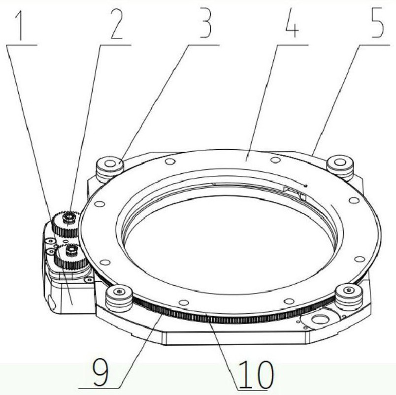
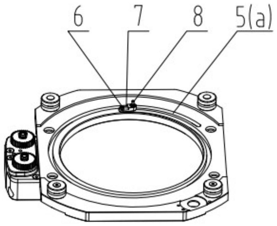
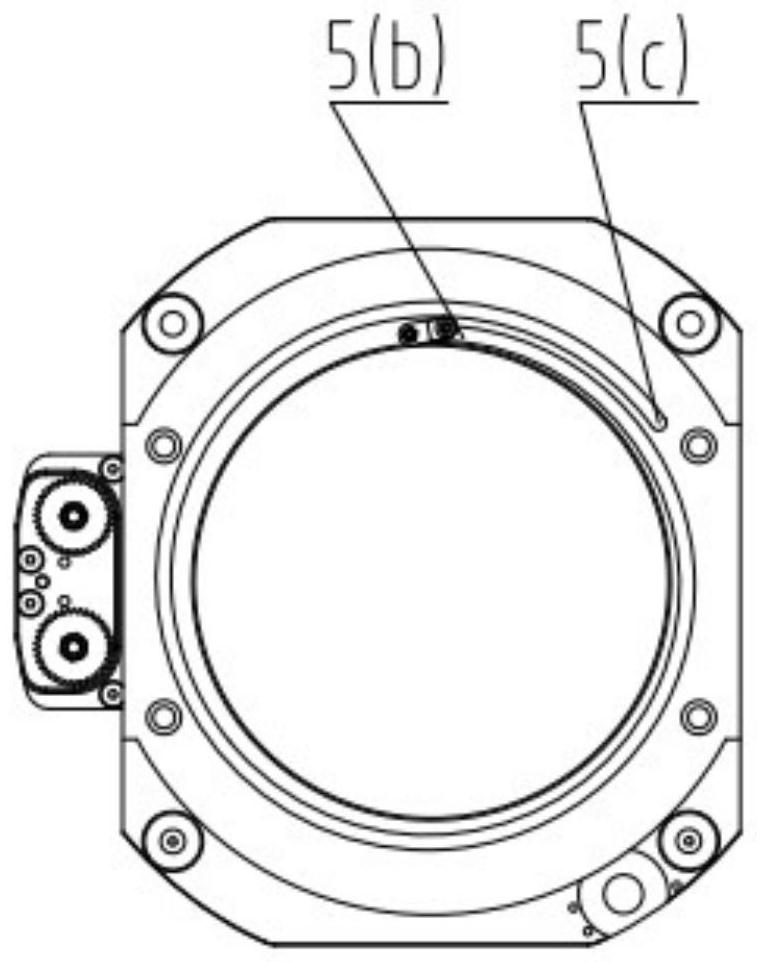
[0019] Such as Figure 1-5 As shown, the circumferential rotation limiting mechanism includes a fixed disk 5, a rotating disk 4 that is rotatably connected to the fixed disk 5, a rotating assembly that makes the rotating disk 4 and the fixed disk 5 rotatably connected, and a device for driving the rotating disk 4 to rotate. The drive assembly is provided with a helical limiting groove 5(a) on the fixed disk 5 or on the rotating disk 4, the inner end of the helix is ​​the starting end 5(b), and the outer end of the helix is ​​the ending end 5(c), The circumferential range of the limit groove 5 (a) is greater than 360°, the upper and lower end surfaces of the rotating disk 4 and the fixed disk 5 are both penetrating and annular, and the inner diameter and outer diameter of the rotating disk 4 are d and D respectively, (D-d) / D <1 / 5, the c...


PUM


Abstract

The invention discloses a circumferential rotation limiting mechanism, which comprises a fixed plate, a rotating plate rotatably connected to the fixed plate, a rotating assembly for rotating the rotating plate and the fixed plate, and a driving assembly for driving the rotating plate to rotate. A helical limiting groove is provided on the fixed disk or the rotating disk, the roller connected to the limiting groove that rolls along the helical extension direction of the limiting groove, and the swinging wheel that is located above the limiting groove and coaxially fixedly connected with the roller The seat, the two ends are respectively rotatably connected with the swing seat and the rotating disk. The physical limit is realized, the transmission is smoother, the risk of jamming is greatly reduced, and the overall volume of the mechanism can be reduced, which is beneficial to non-destructive testing in a small space.

Description

technical field [0001] The invention belongs to the field of nuclear power detection equipment, and in particular relates to a circumferential rotation limiting mechanism. Background technique [0002] In non-destructive testing activities, when testing rotary workpieces such as shafts and cylinders, in order to achieve full coverage of the circumferential scanning range, the design of the mechanical structure often requires a circumferential motion range greater than 360° (generally at least 380° °), that is, to ensure that the probe carried on the circumferential motion mechanism has a certain scanning coverage. The previous designs often used multiple position sensors (generally there are three sensors of zero point, positive limit and negative limit) to detect the position of the circumferential movement. This method has two obvious disadvantages: 1) Due to the In general, it is necessary to arrange drag chains to accommodate cables. In some special cases, such as when ...

Claims


Application Information

Patent Timeline
Patent Type & Authority Patents(China)
IPC IPC(8): F16M11/04G01D11/00
CPCF16M11/04G01D11/00F16M2200/02
Inventor 张鹏飞吕天明王彬林戈曾晨明严志刚
Owner CGNPC INSPECTION TECH
Why Eureka
Try Eureka