Supercharge Your Innovation With Domain-Expert AI Agents!

Narrow-frame LED panel lamp

A technology of LED panel light and narrow frame, which is applied in the direction of lighting auxiliary devices, lighting and heating equipment, fixed lighting devices, etc. It can solve the problem of poor uniformity of light in the center of the light-emitting panel, increased difficulty in light distribution and splicing, and poor visual effects, etc. problem, to achieve the effect of reducing the width

Pending Publication Date: 2021-02-26
CHANGXING FANYA WISDOM LIGHTING CO LTD
View PDF0 Cites 2 Cited by
  • Summary
  • Abstract
  • Description
  • Claims
  • Application Information

AI Technical Summary

Problems solved by technology

[0002] There are mainly two structures used in existing panel lamps, one is to set the light source from the side of the light-emitting panel, and the other is to set the light source from the back side of the light-emitting panel. The light attenuation leads to poor light uniformity in the center of the luminous panel, and although the light attenuation uniformity of the second method will be higher than the first method, in order to ensure uniformity, the thickness of the lamp is usually required to be larger, and in order to ensure the panel Uniform lighting also requires setting a wider frame to fix the light-emitting panel. This method has poor visual effects after actual installation. At the same time, due to the large width of the non-luminous frame, it will also make it difficult to carry out light distribution splicing in indoor lighting design. increase

Method used


Image

  • Narrow-frame LED panel lamp
  • Narrow-frame LED panel lamp

Examples


Embodiment Construction

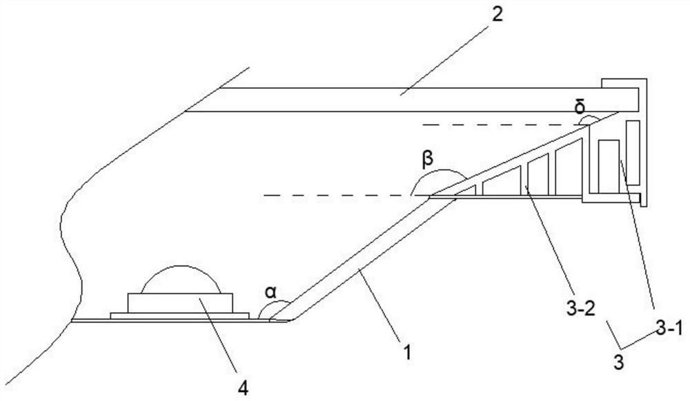
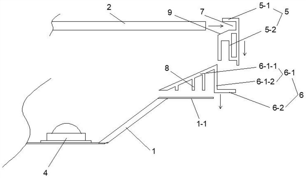
[0019] The present invention will be described in further detail below in conjunction with the accompanying drawings.

[0020] Such as figure 1 , figure 2 As shown, this embodiment includes a chassis 1, a light-emitting panel 2, and a fixed frame 3, wherein the fixed frame 3 includes a surrounding edge 5-1 arranged outside the light-emitting panel 2, and the width of the surrounding edge 5-1 is less than or equal to 6 mm , this embodiment is preferably implemented with a size less than or equal to 5 mm. In the prior art, the width of the surrounding edge 5-1 is generally set within a size range of 20±1 mm. There are at least two bar-shaped light source groups 4 arranged in parallel on the chassis 1. The number of bar-shaped light source groups 4 is determined according to the specifications of the lamps. The number is at least two, and they are fixedly connected to the chassis 1 through screws. A heat-conducting silicone grease layer is arranged between the plate body and t...


PUM

PropertyMeasurementUnit
Widthaaaaaaaaaa
Angleaaaaaaaaaa
Angleaaaaaaaaaa

Abstract

A narrow-frame LED panel lamp comprises a base plate, a light-emitting panel and a fixed frame, the fixed frame comprises a surrounding edge arranged on the outer side of the light-emitting panel, andthe width of the surrounding edge is smaller than or equal to 6 mm. The narrow-frame LED panel lamp has the advantage that the width of the frame is greatly reduced on the premise that the light-emitting uniformity of the light-emitting panel is guaranteed.

Description

technical field [0001] The technical field of LED lamps of the present invention particularly relates to a narrow frame LED panel lamp. Background technique [0002] There are mainly two structures used in existing panel lamps, one is to set the light source from the side of the light-emitting panel, and the other is to set the light source from the back side of the light-emitting panel. The light attenuation leads to poor light uniformity in the center of the luminous panel, and although the light attenuation uniformity of the second method will be higher than the first method, in order to ensure uniformity, the thickness of the lamp is usually required to be larger, and in order to ensure the panel Uniform lighting also requires setting a wider frame to fix the light-emitting panel. This method has poor visual effects after actual installation. At the same time, due to the large width of the non-luminous frame, it will also make it difficult to carry out light distribution...

Claims


Application Information

Patent Timeline
IPC IPC(8): F21S8/00F21V5/00F21V19/00F21V21/00F21Y115/10
CPCF21S8/00F21V19/001F21V21/00F21V5/00F21Y2115/10
Inventor 周勇涛曾斌章旭阳
Owner CHANGXING FANYA WISDOM LIGHTING CO LTD
Features
  • R&D
  • Intellectual Property
  • Life Sciences
  • Materials
  • Tech Scout
  • Unparalleled Data Quality
  • Higher Quality Content
  • 60% Fewer Hallucinations
Learn More