Sensing control system

A sensor control and delay control technology, applied in the field of sensor control systems, can solve the problems of lack of realism, insecurity, huge differences, etc., and achieve the effect of more accurate, real and effective sensed sound signals, and improved safety.

Active Publication Date: 2021-02-26
北京名扬新时代科技发展有限公司
View PDF10 Cites 0 Cited by
  • Summary
  • Abstract
  • Description
  • Claims
  • Application Information

AI Technical Summary

Problems solved by technology

[0002] In order to enhance people's national defense awareness of defending the country and safeguarding peace, military training for soldiers and the general public is becoming more and more important. In the process of military training, it is easy to achieve gun shooting training. Domestic soldiers all use real guns and live ammunition for training. The advantage is of course that the operation is real and the training effect is good, but the obvious disadvantage is that it is expensive and extremely unsafe.
[0003] In recent years, due to the development of photoelectric technology, more types of simulated guns have appeared on the market. Generally, simulated guns can simulate the sound of real gun shooting and the impact recoil during operation, but the simulated sound and simulated recoil are still very different from real shooting.
Not only that, the existing simulated guns also have the use of laser instead of ammunition for shooting during amusement or training, but when emitting laser, because the laser is triggered and launched, that is, the laser is launched instantaneously when the trigger is pulled, so it is different from real shooting. There is a big difference and lacks a sense of reality, so it is very lacking in military training

Method used


Image

  • Sensing control system

Examples


Embodiment approach

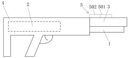
[0045] According to one embodiment of the present invention, there is an RC delay circuit or a time relay electrically connected to the sensing module (ie each sensor) and the laser transmitter 1 on the circuit board. In this way, when the sensor senses the signal and converts it into an electrical signal, it can realize the delay control of the laser transmitter to emit laser pulses through the RC delay circuit or time relay.

[0046] In this embodiment, in order to make the emission of the laser pulse as much as possible the same as the emission effect of the actual bullet warhead, the laser pulse emitted by the laser transmitter 1 should be after the circuit board receives the sound signal or receives the sound signal and the recoil signal. A delay of 3ms triggers the laser transmitter 1 to emit laser pulses.

[0047] According to the above-mentioned embodiment of the present invention, even if the laser is used to replace the real warhead, it can ensure that the trainers h...


PUM


Abstract

The invention relates to the technical field of control or adjusting systems, and particularly provides a sensing control system. The sensing control system comprises a laser emitter arranged on the outer wall of a gun barrel of a gun and a delay control module arranged in a gun body of the gun and electrically connected with the laser emitter. The delay control module controls the laser emitter to emit laser pulses in a delay mode according to signals emitted when the gun shoots a blank ammunition. According to the sensing control system, when a trigger firing pin of the gun is pulled to strike a primer, the gun can normally ignite the blank ammunition, so that it can be ensured that the gun provides a real shooting sound effect and a recoil effect, a real shooting effect is realized during training, and a soldier adapts to the shooting environment and has a higher training score. The delay control module is used for controlling laser pulse emission in a delay mode, the shooting training of an individual soldier can be more real and closer to the shooting training of the gun, the bullet shooting feeling is achieved, and therefore the sensing control system is more suitable for military training. In addition, by means of a two-section type air guide pipe, the bore pressure is effectively increased to push out a cartridge case more smoothly, and recoil force is vivid.

Description

technical field [0001] The invention relates to the technical field of control or regulation systems, in particular to a sensor control system attached to firearms using blank bullets for laser simulation shooting. Background technique [0002] In order to enhance people's national defense awareness of defending the country and safeguarding peace, military training for soldiers and the general public is becoming more and more important. In the process of military training, it is easy to achieve gun shooting training. The domestic soldiers all use real guns and live ammunition for training. The advantage is of course that the operation is real and the training effect is good, but the obvious disadvantages are that it is expensive and extremely unsafe. [0003] In recent years, due to the development of optoelectronic technology, more types of simulated guns have appeared on the market. Generally, simulated guns can simulate the sound of real gun shooting and the impact recoil...

Claims


Application Information

Patent Timeline
Patent Type & Authority Applications(China)
IPC IPC(8): F41A33/02
CPCF41A33/02
Inventor 李雷付为工
Owner 北京名扬新时代科技发展有限公司
Why Eureka
Try Eureka