
Imaging detection method and system

An imaging detection and imaging device technology, which is applied in measuring devices, line-of-sight measurement, distance measurement, etc., can solve the problems that one photo cannot be covered, the imaging target area is large, and the mosaic stitching of multiple images is difficult

Pending Publication Date: 2021-02-26
CHENGDU ZHONGXIN HUARUI TECH CO LTD
View PDF0 Cites 5 Cited by
  • Summary
  • Abstract
  • Description
  • Claims
  • Application Information

AI Technical Summary

Problems solved by technology

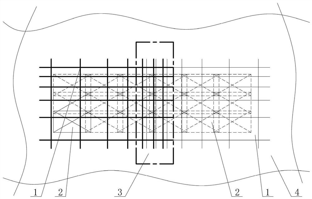
[0008] The purpose of the present invention is to provide a new imaging detection system and its method, using the imaging detection system according to the proposed detection method, to solve the problem that in the existing imaging detection technology, the imaging target area is relatively large, and one photo cannot cover the detection area. range, and the lack of image features on the surface to be detected requires multiple imaging, and the mosaic stitching of multiple images is difficult and the mosaic accuracy is low

Method used


Image

  • Imaging detection method and system

Examples


Embodiment 1

[0115] The embodiment of the imaging detection system and its method in the field of imaging detection of engineering building defects chooses the imaging detection of railway tunnel lining defects.

[0116] The equipment used includes an imaging system including an imaging device, a background conformation device, and a control device. Wherein the background conformation device is used to generate a background pattern and project the background pattern to the imaging detection area; the imaging device includes a camera and a camera correction pattern conformation device, an attitude sensor and a position sensor; a camera, a camera correction pattern conformation device, an attitude sensor and a position sensor The sensors are all rigidly connected to the structural components of the imaging device; the background conformation device and imaging device used have been calibrated. The correction pattern conformation device is used to generate a correction pattern, and the laser ...

Embodiment 2

[0141] The embodiment of the imaging detection system and its method in the field of imaging detection of engineering building defects selects the imaging detection of building surface defects in an open-air environment.

[0142] The equipment used includes an imaging system including an imaging device, a background conformation device, and a control device. The background conformation device and imaging device used have been calibrated.

[0143] The control unit is integrated with the imaging unit. The correction pattern formed by the second group of laser line projectors and the second group of laser rangefinders is consistent with the field of view of the image collected by the camera of the imaging device, and the correction pattern area projected on the surface to be imaged and detected during imaging is covered with the imaging area; The correction pattern is the correction grid line and point pattern projected by the second group of laser line projectors, the second gr...


PUM


Abstract

The invention discloses an imaging detection system and method, and aims to solve the problems that an imaging area lacks matching characteristics and needs more than two times of imaging for effective coverage, and geometric parameters of flaws, defects and other diseases in an image need to be accurately measured. A background conformation device generates a laser background pattern and projectsthe background pattern to an imaging detection area. An imaging device is composed of a camera and a corrected pattern projection device. The imaging device acquires a target image having a correctedpattern and a background pattern. When one background conformation device cannot cover the imaging detection area, a plurality of background conformation devices are used for projecting background patterns, the background patterns projected by the plurality of background conformation devices are overlapped in the imaging area, and the space combination relation of the background patterns formed by the plurality of background conformation devices is not changed in the imaging process. Image geometric correction processing is completed according to the corrected pattern projected by the imagingdevice, and multi-image mosaic matching is completed based on the background pattern.

Description

technical field [0001] The invention belongs to the technical field of imaging detection, and in particular relates to imaging detection of diseased surface defects and diseases of buildings (such as tunnels, underground engineering, slopes, building surfaces, road surfaces, etc.). Background technique [0002] There is a demand for surface defect detection and measurement in many fields. Imaging methods to detect surface defects have the following limitations in specific imaging inspection operations: [0003] 1. A photo cannot cover the range to be detected, that is, the range to be detected cannot be covered by taking an image. Multiple images need to be taken to complete the coverage of the area to be detected. The problem is that when multiple images in the area to be detected need to be mosaiced to form a large image, it is difficult to determine the position of multiple images in the detection area due to the lack of location information features in the area to be d...

Claims


Application Information

Patent Timeline
IPC IPC(8): G01N21/88G01C11/00G01C3/00
CPCG01N21/88G01C11/00G01C3/00
Inventor 秦军秦捷
Owner CHENGDU ZHONGXIN HUARUI TECH CO LTD
Learn More