Cable connecting device capable of being rotationally adjusted

A technology of connection device and rotation adjustment, which is applied in the direction of cable joints, etc., can solve problems such as affecting testing and poor connection, and achieve the effects of saving trouble, stable communication, and simple operation

Active Publication Date: 2021-02-26
GUIZHOU POWER GRID CO LTD
View PDF11 Cites 2 Cited by
  • Summary
  • Abstract
  • Description
  • Claims
  • Application Information

AI Technical Summary

Problems solved by technology

[0003] In coaxial cable core or control cable core on-off test, optical fiber core test and Ethernet cable test, the cooperation of the host and the slave is required. The host and the slave need to be connected through cables. The traditional connection method often There is a phenomenon of poor connection, which affects the on-site test, so it is necessary to design a connection device to ensure the stable connection between the master and the slave

Method used


Image

  • Cable connecting device capable of being rotationally adjusted
  • Cable connecting device capable of being rotationally adjusted
  • Cable connecting device capable of being rotationally adjusted

Examples


Embodiment 1

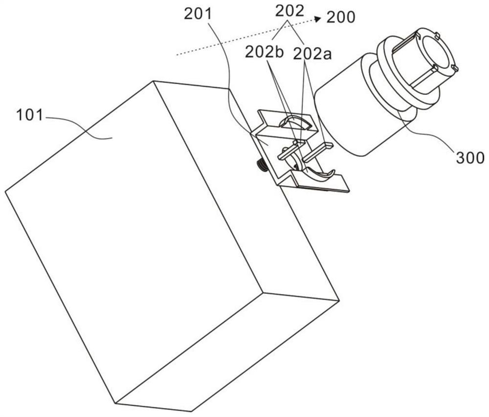
[0030] refer to Figure 1~3 , is the first embodiment of the present invention, which provides a rotatable and adjustable cable connection device, which includes a host 101, a rotating assembly 200 and a first plug-in 300, the first plug-in 300 can be connected with the rotating assembly 200 The host 101 is movably connected, and the angle of the first plug-in 300 can be controlled by the rotation of the rotation assembly 200 .

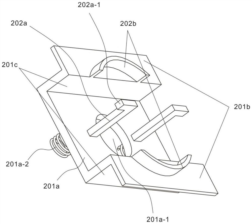
[0031] The rotation assembly 200 includes a support 201 and a limiter 202. The support 201 is used to connect the host 101. The limiter 202 is used to connect the first plug-in 300 and the first plug-in 300 can be adjusted by rotation, specifically, the first plug-in 300 A sleeve 301 is included, and the bottom end of the sleeve 301 can be movably connected with the host 101 by being connected with the stopper 202 .

[0032] Further, the supporting member 201 includes a bottom plate 201a, a supporting plate 201b and a connecting plate 201c. A spring ...

Embodiment 2

[0037] refer to Figure 4~7 , is the second embodiment of the present invention, this embodiment is based on the previous embodiment, and also includes a second plug-in 400 and a slave 102, the second plug-in 400 is fixedly connected to the slave 102, the second plug-in 400 is connected to the first plug-in 300 Can be matched with each other.

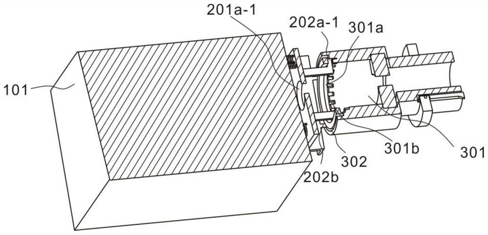
[0038] The first plug-in 300 also includes a nested sleeve 303, a first cable 305 and a slider 306, the second plug-in 400 includes a connecting cylinder 401, a barrier 402 and a second cable 403, one end of the sleeve 301 is connected to the host 101, and the other One end is fixedly connected to the nested sleeve 303, the sleeve 301 and the nested sleeve 303 are connected internally and are coaxial, the first cable 305 is located inside the sleeve 301 and the nested sleeve 303 and is also coaxial, the first line One end of the cable 305 is fixed on the main machine 101, then passes through the round hole 201a-1, the sleeve 301 and the ...


PUM


Abstract

The invention discloses a cable connecting device capable of being rotationally adjusted. The cable connecting device comprises a host, a rotating assembly and first plug-in units, wherein the rotating assembly is movably arranged on the host and comprises a supporting piece and a limiting piece, one side of the supporting piece is connected to the host, and the other side of the supporting pieceis connected with the limiting piece; and each first plug-in unit comprises a sleeve, and the sleeve is movably connected with the host through a rotating assembly. By designing an adjusting device between the host and the plug-in units, the angle of the plug-in units can be adjusted through rotation before the plug-in units are connected, so clamping connection between the two plug-in units is facilitated, clamping difficulty and poor contact are avoided, communication between the host and a slave after connection is more stable, clamping connection can be achieved only by pushing two ends during connection, operation is easy, practicability is high, and troubles are greatly reduced for workers.

Description

technical field [0001] The invention relates to the technical field of cable connection, in particular to a rotatably adjustable cable connection device. Background technique [0002] At present, the protection and automation professional team is responsible for the maintenance of 60 stations of 110kV and above in Liupanshui Power Grid, which involves regular inspection, defect elimination, overhaul technical transformation, infrastructure acceptance, etc. The work site needs to frequently use laser lighting pens and network testers , optical power meter, optical multimeter, digital multimeter and other cable test tools, to check the fiber core of optical cable, Ethernet cable, secondary cable core, coaxial cable and other cables, including cable on-off test, optical fiber core on-off Testing, optical fiber attenuation testing, Ethernet line transmission reliability testing, process quality testing, etc.; [0003] In coaxial cable core or control cable core on-off test, opt...

Claims


Application Information

Patent Timeline
Patent Type & Authority Applications(China)
IPC IPC(8): H02G15/18
CPCH02G15/18
Inventor 陈刚付同福赵轩黄力王文华黄照厅张礼波郁金松胡勇潘盛贵施武作沈立胜王涛何进锋龙志张建行管进袁勇
Owner GUIZHOU POWER GRID CO LTD
Why Eureka
Try Eureka