Refrigerated display cabinet

A technology for display cabinets and cabinets, which is applied to display cabinets, display stands, display hangers, etc. It can solve the problems of large temperature difference in wine storage chambers and unfavorable wine storage, and achieve uniform air flow, simple structure, and scientific design Effect

Active Publication Date: 2021-03-02
AEGLOS REFRIGERATION LTD
View PDF4 Cites 3 Cited by
  • Summary
  • Abstract
  • Description
  • Claims
  • Application Information

AI Technical Summary

Problems solved by technology

Although such a structure can realize the air circulation between the wine storage chamber and the accommodation chamber through the fan assembly, the air in the wine storage chamber directly enters into the accommodation chamber from the back of the wine storage chamber, and the wine storage chamber The temperature difference between the upper and lower layers is large, which is not conducive to the storage of wine

Method used


Image

  • Refrigerated display cabinet
  • Refrigerated display cabinet
  • Refrigerated display cabinet

Examples


Embodiment 1

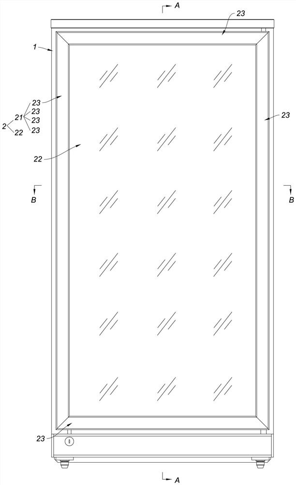
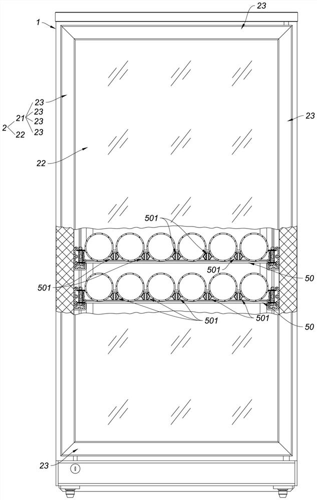
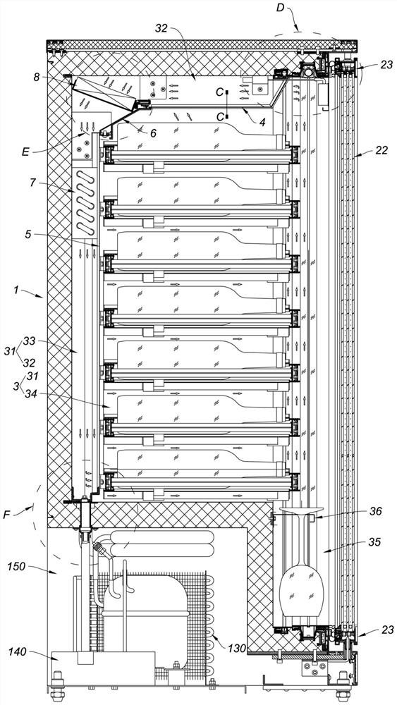
[0033] Such as figure 1 , figure 2 , image 3 , Figure 4 , Figure 6 , Figure 7As shown, this embodiment is a refrigerated display cabinet, which includes a cabinet body 1 and a cabinet door 2, and an accommodation chamber 3 is formed in the cabinet body 1, and the mouth of the accommodation chamber 3 is located on the front elevation of the cabinet body 1; The cabinet door 2 is installed on the cabinet body 1, and the cabinet door 2 is used to close the mouth of the accommodation chamber 3; it also includes an air inlet partition 4, an air duct partition 5, an installation profile 6, an evaporator 7 and an evaporation fan 8; where:

[0034] The air inlet baffle 4 and the air duct baffle 5 are all installed in the accommodation chamber 3, and the top edge of the air duct baffle 5 and the rear side of the air inlet baffle 4 are connected together through the installation profile 6 , the air inlet partition 4, the installation profile 6 and the air duct partition 5 sepa...

Embodiment 2

[0052] This embodiment is a refrigerated display cabinet with double doors. The difference between this embodiment and Embodiment 1 is that: Figure 14 , Figure 15 , Figure 16 , Figure 17 As shown, the cabinet body 100 is also provided with a middle partition column 200, which separates the opening of the receiving cavity to form a left cavity opening and a right cavity opening, and the cabinet door 300 includes a left cabinet door 3001 And the right cabinet door 3002, the left cabinet door 3001 and the right cabinet door 3002 are all installed on the cabinet body 100, the left cabinet door 3001 is used to close the left cavity opening of the storage chamber, and the right cabinet door 3002 is used to close the right cavity opening of the storage cavity The air duct partition 400 includes a left air duct partition 4001 and a right air duct partition 4002; a middle column 500 is installed behind the chamber of the accommodating cavity, and the left air duct partition 4001 ...


PUM


Abstract

The invention relates to a refrigeration display cabinet, and the cabinet comprises a cabinet body and a cabinet door, wherein a containing cavity is formed in the cabinet body. The cabinet door is used for closing the opening of the accommodating cavity. The cabinet further comprises an air inlet partition plate, an air duct partition plate, an installation profile, an evaporator and an evaporation fan. The air inlet partition plate and the air duct partition plate are both installed in the containing cavity, the top edge of the air duct partition plate and the rear side edge of the air inletpartition plate are connected together through the installation sectional material, and the containing cavity is divided into an air duct cavity and a display cavity through the air inlet partition plate, the installation sectional material and the air duct partition plate. The face, facing the display cavity, of the installation profile is an air guide face which gradually inclines upwards fromthe rear face of the containing cavity to a cavity opening of the containing cavity, an air inlet hole is formed in the air inlet partition plate, and an air outlet hole is formed in the air duct partition plate. The evaporation fan is obliquely installed at the communication position of the air blocking channel and the air inlet channel, and the evaporator is installed in the air blocking channel. The temperature difference between the upper layer and the lower layer in the display cavity can be almost ignored, and storage of wine beverages is facilitated.

Description

technical field [0001] The invention relates to the technical field of refrigerators, in particular to a refrigerator display cabinet for storing wine or beverages. Background technique [0002] At present, the refrigerated display cabinets for storing wine or beverages on the market are as the technical scheme described in Chinese Patent Application No. 2013106888515, titled "Constant Temperature Wine Cabinet and Temperature Control Method Thereof"; And the fan assembly, in this technical solution, an accommodating chamber is formed between the air duct cover plate and the rear wall of the box, and the fan assembly is located in the accommodating chamber and installed on the air duct cover plate. Although such a structure can realize the air circulation between the wine storage chamber and the accommodation chamber through the fan assembly, the air in the wine storage chamber directly enters into the accommodation chamber from the back of the wine storage chamber, and the w...

Claims


Application Information

Patent Timeline
Patent Type & Authority Applications(China)
IPC IPC(8): A47F3/04A47F7/00A47F11/10
CPCA47F3/0408A47F3/0482A47F3/043A47F7/00A47F3/001
Inventor 钱小明杨汉洲宋声文莫求告
Owner AEGLOS REFRIGERATION LTD
Why Eureka
Try Eureka