Artificial respiration device for cardiology department nursing

A kind of artificial respiration, cardiology technology, applied in respirator, transportation and packaging, drug equipment and other directions, can solve the problem of rapid hammering of gas

Inactive Publication Date: 2021-03-02
赵雪溢
View PDF1 Cites 1 Cited by
  • Summary
  • Abstract
  • Description
  • Claims
  • Application Information

AI Technical Summary

Problems solved by technology

However, this patent cannot quickly hammer out the gas by hammering, thereby helping the gas to blow out quickly and help breathing.

Method used


Image

  • Artificial respiration device for cardiology department nursing
  • Artificial respiration device for cardiology department nursing
  • Artificial respiration device for cardiology department nursing

Examples


specific Embodiment approach 1

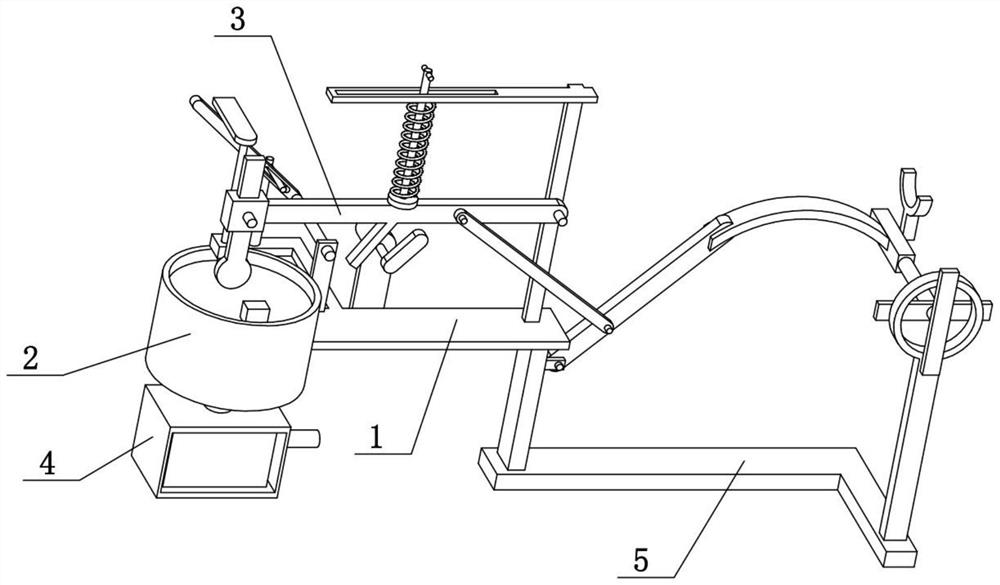
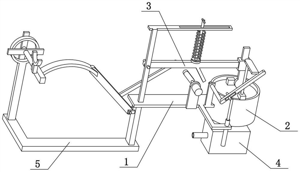
[0027] Combine below Figure 1-7 To illustrate this embodiment, the present invention relates to the field of cardiology nursing, more specifically, an artificial respiration device for cardiology nursing, including a plate 1, a cylinder 2, a one-way valve 201, a piston 202, a pull rod 204, and a swing beam 3 1. The hammer head rod 301 and the vertical rod 307. The present invention can quickly hammer out the gas by hammering, and then help the gas to blow out quickly to help breathing.

[0028] The left end of the plate 1 is fixedly connected with a cylinder 2, the cylinder 2 is vertically slidably connected with a piston 202, the right end of the plate 1 is fixedly connected with a vertical rod 307, and the right end of the swing beam 3 is hinged at the middle of the vertical rod 307, swinging A hammerhead rod 301 is provided at the left end of the beam 3, and the hammerhead rod 301 is located above the piston 202, and a tie rod 204 is fixedly connected to the upper side of ...

specific Embodiment approach 2

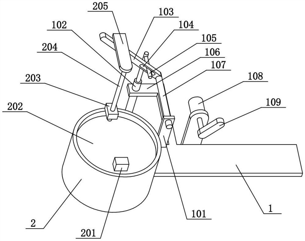
[0030] Combine below Figure 1-7 Illustrate the present embodiment, described cardiology nursing artificial respiration device also comprises fixed cover 302, and fixed cover 302 is fixedly connected to the left end of pendulum beam 3, and hammer head rod 301 is slidably connected on fixed cover 302, and fixed cover 302 is threaded. A fastening screw is connected, and the fastening screw is pushed against the hammer head rod 301 . The hammer head rod 301 can slide up and down relative to the fixed sleeve 302, thereby adjusting the distance from which the hammer head rod 301 protrudes from the lower side of the swing beam 3, and then adjusting the force of the hammer head rod 301 hammering on the piston 202, and then adjusting the gas pressure in the cylinder 2. The degree of rapid extrusion.

specific Embodiment approach 3

[0032] Combine below Figure 1-7 Illustrate present embodiment, described cardiology department nursing artificial respiration device also comprises motor 108, circumference rotating bar 109, slotted hole 303, spring cover bar 304, retaining pin 305, slotted hole bar 306 and inclined column 309, swing beam 3 The middle part of the lower side is fixedly connected with a slanted column 309, and the flat panel 1 is fixedly connected with a motor 108, and the output shaft of the motor 108 is fixedly connected with a circular rotating rod 109, which is located on the right side of the slanted column 309, and the upper end of the vertical rod 307 Fixedly connected with a long hole rod 306, the long hole rod 306 is provided with a long hole 303, the upper middle part of the swing beam 3 is fixedly connected with a spring sleeve rod 304, the top of the spring sleeve rod 304 is inserted on the elongated hole 303, and the spring sleeve rod The upper end of 304 is fixedly connected with ...


PUM


Abstract

The invention relates to the field of cardiology department nursing, in particular to an artificial respiration device for cardiology department nursing, which comprises a flat plate, a cylinder, a one-way valve, a piston, a pull rod, a swing beam, a hammer head rod and a vertical rod, and can be used for quickly hammering out gas through hammering so as to help the gas to be quickly blown out tohelp respiration. A cylinder is fixedly connected to the left end of the flat plate, a piston is vertically connected to the cylinder in a sliding mode, a vertical rod is fixedly connected to the right end of the flat plate, the right end of the swing beam is hinged to the middle of the vertical rod, a hammer rod is arranged at the left end of the swing beam and located above the piston, and a pull rod is fixedly connected to the upper side of the piston. The artificial respiration device for nursing in the department of cardiology further comprises a fixing sleeve, the fixing sleeve is fixedly connected to the left end of the swing beam, the hammer head rod is connected to the fixing sleeve in a sliding mode, a fastening screw is connected to the fixing sleeve through threads, and the fastening screw abuts against the hammer head rod.

Description

technical field [0001] The invention relates to the field of cardiology nursing, in particular to an artificial respiration device for cardiology nursing. Background technique [0002] The application number is CN201721006379.2, which discloses a mobile breathing device for internal medicine, which includes a main body of the mobile breathing device and an air collection tank. The front end of the main body of the mobile breathing device is fixedly equipped with a rotary switch, a finger dial and operation buttons. The rightmost end of the main body of the mobile breathing device is fixedly equipped with a carrier, and the carrier is moved to place a breathing mask, and the breathing mask is fixedly connected to the right end of the main body of the movable breathing device through an outlet pipe. The lower end is fixedly installed with a base bracket, the lower end of the base bracket is connected with a load placement plate, the lower end of the load placement plate is fix...

Claims


Application Information

Patent Timeline
Patent Type & Authority Applications(China)
IPC IPC(8): A61M16/00A61M16/10B01D46/00B01D46/30
CPCA61M16/00A61M16/0003A61M16/0072A61M16/105B01D46/30A61M2205/75B01D46/88
Inventor 赵雪溢
Owner 赵雪溢
Why Eureka
Try Eureka