Cast-in-place mold for building bridge stand column pouring

A bridge and column technology, applied in the field of cast-in-place molds, can solve problems such as mold punctures, safety hazards, support failures, etc., and achieve the effects of uniform contact force, avoiding damage, and more contact points

Inactive Publication Date: 2021-03-02
施娟丽
View PDF6 Cites 1 Cited by
  • Summary
  • Abstract
  • Description
  • Claims
  • Application Information

AI Technical Summary

Problems solved by technology

[0003] In the above operation steps, the steel rod used for external support is in point contact with the mold. Due to the large amount of poured concrete, when the mold is unstable, the point contact between the mold and the steel rod will Cause the mold to be punctured, eventually cause the support to fail, the mold collapses, and there is a big safety hazard

Method used


Image

  • Cast-in-place mold for building bridge stand column pouring
  • Cast-in-place mold for building bridge stand column pouring
  • Cast-in-place mold for building bridge stand column pouring

Examples


Embodiment 1

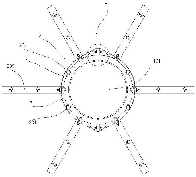
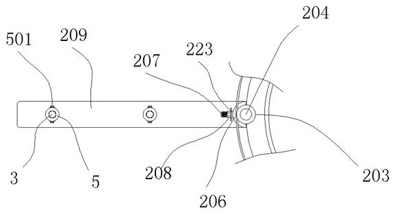
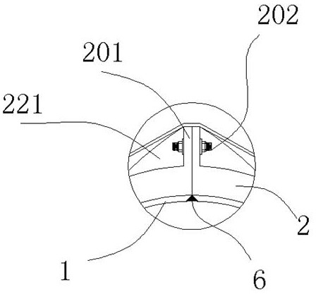
[0032] A cast-in-situ mold for building bridge columns, including two templates 1 that can be spliced ​​and assembled. The template 1 is made of Q235 ordinary carbon structural steel plate with a wall thickness of 16mm; before pouring, it is necessary to paint the inside of the template 1 with an oil film , or covered by a plastic film, to facilitate demoulding in the later stage; two templates 1 are combined to form a mold cavity 101 for pouring concrete, and an arc-shaped reinforcing plate 2 is welded at the outer wall of the template 1, and the reinforcing plate 2 The two ends of the ear plates 201 are bent to form ear plates 201, and bolts 202 are installed between the two ear plates 201. After the bolts 202 are tightened, the assembly of the two templates 1 is completed; block; a plurality of arc-shaped positioning grooves 203 are distributed circularly on the outer side of the reinforcing plate 2, and on the outer side of the template 1, a plurality of vertical rods 204 a...

Embodiment 2

[0034] After the two modules 1 are spliced ​​together, a V-shaped card slot is formed at the joint position, and a rubber sealing strip 6 is arranged in the V-shaped card slot formed by the combination, and the sealing strip 6 is squeezed and deformed; the above The structure can avoid leakage when pouring concrete.

Embodiment 3

[0036] A steel cable 7 is assembled between the exteriors of a plurality of said vertical rods 204, and said steel cable 7 is helically wound on the exteriors of a plurality of said vertical rods 204; Ribs 221 are arranged between the plates 2; the steel cables 7 can apply a tightening force between a plurality of vertical rods 204, and form a whole with the vertical rods 204 that originally apply external pressure on the outside alone, and apply a whole The force of adduction avoids expansion and leakage at the joint position of the formwork.


PUM


Abstract

The invention discloses a cast-in-place mold for pouring a building bridge upright post, which comprises two templates capable of being spliced and assembled, the templates adopt common carbon structural steel plates, and the wall thickness is 8mm-22mm; before pouring, an oil film needs to be brushed in the formwork or covered with a plastic film, and later demolding is facilitated; the two formworks are combined to form a formwork cavity for pouring concrete, arc-shaped reinforcing plates are welded to the outer walls of the formworks, the two ends of each reinforcing plate are bent to form lug plates, bolts are assembled between the two lug plates, and the two formworks are assembled after the bolts are tightened; a plurality of reinforcing plates are arranged in parallel up and down; the device can realize stable placement.

Description

technical field [0001] The invention relates to a cast-in-place mold for pouring upright columns of building bridges. Background technique [0002] In the construction of large buildings and bridges, it is often necessary to pour concrete columns with large diameters (i.e. load-bearing columns); the existing pouring method is to build a mold on the ground to accommodate the concrete, and the outside of the mold is supported by steel rods to maintain the mold. The vertical state, then pour concrete, vibrate, wait for it to dry, and then remove the mold. [0003] In the above operation steps, the steel rod used for external support is in point contact with the mold. Due to the large amount of poured concrete, when the mold is unstable, the point contact between the mold and the steel rod will Cause the mold to be punctured, eventually cause the support to fail, the mold collapses, and there is a big potential safety hazard. [0004] Based on the above problems, we designed a...

Claims


Application Information

Patent Timeline
Patent Type & Authority Applications(China)
IPC IPC(8): E01D21/00E01D19/02
CPCE01D21/00E01D19/02
Inventor 施娟丽金永年
Owner 施娟丽
Why Eureka
Try Eureka