Buffering device used for controlling movement speed of actuator cylinder

A technology of movement speed and buffer device, applied in the direction of fluid pressure actuating device, chassis, etc., it can solve the problems that the rubber pad is easy to fall off or age, it is not enough to overcome the friction torque, and it is difficult to meet the structural requirements, so as to achieve the inertia impact force Small size, simple structure, and the effect of reducing mechanical impact energy

Pending Publication Date: 2021-03-02
SICHUAN LINGFENG AVIATION HYDRAULIC MACHINERY
View PDF0 Cites 2 Cited by
  • Summary
  • Abstract
  • Description
  • Claims
  • Application Information

AI Technical Summary

Problems solved by technology

The main disadvantage of the rubber pad cushioning is: the severe impact force and the heat generated are quite severe tests on the bonding force between the rubber pad and the piston. Over time, the rubber pad is easy to fall off or age, which affects the reliable locking of the lock mechanism.
The main disadvantages of the hydraulic shock absorbing device are: in the case of relatively strict structural size or quality index requirements, due to the troublesome structural design of the throttling setting at the left end, it is generally difficult to meet the structural requirements; in order to achieve a good cushioning effect , oil will be added to the right end for damping, there will be two kinds of media in the whole system, and an accumulator equivalent to storing hydraulic media needs to be designed, which is difficult to control the whole system
When starting the lowering action again, if the starting torque of the motor is small, it is not enough to overcome the friction torque generated by the occlusal force, resulting in the failure of the actuator to extend

Method used


Image

  • Buffering device used for controlling movement speed of actuator cylinder
  • Buffering device used for controlling movement speed of actuator cylinder

Examples


Embodiment Construction

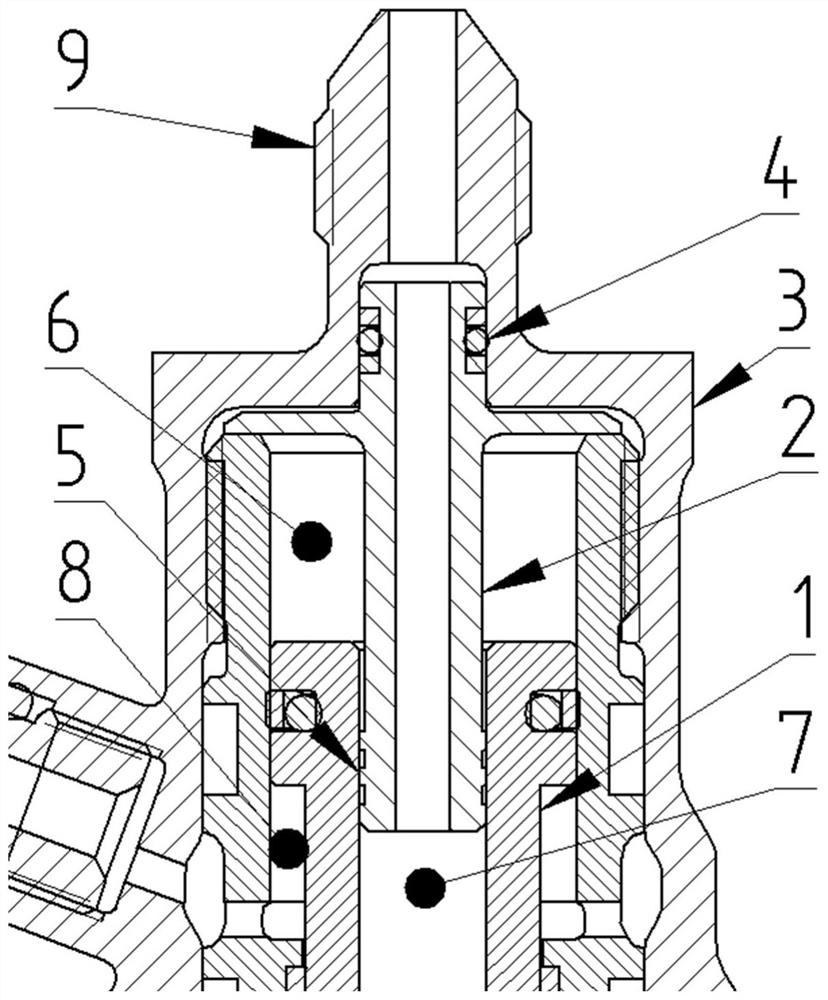
[0013] refer to figure 1. In the preferred embodiment described below, a buffer device for controlling the movement speed of the actuator includes: a piston rod 1 integrated in the outer cylinder 3 of the actuator and assembled in the locking chamber 6, and the piston rod 1 is made of The blind hole chamber 7 is characterized in that: the upper lock chamber 6 is equipped with a damper tube 2 passing through the O-shaped sealing ring 4, sealed in the lock nozzle of the actuator, and connected to the oil flow path of the lock nozzle; On the circumference of the sliding section of the damping tube 2, there is a cut-off ring groove 5 that moves in the direction of the blind hole 7 to adjust the movement distance between the damping tube 2 and the piston rod 1; when the piston rod 1 extends downward, the hydraulic pressure The oil enters the damping tube 2 from the locking nozzle 9, and enters the blind cavity 7 of the piston rod 1 along the damping tube 2. After the blind cavity ...


PUM


Abstract

The invention discloses a buffering device for controlling the movement speed of an actuator cylinder. The reliability of a locking device mechanism can be improved. The buffering device is achieved through the following technical scheme that an upper locking cavity is communicated with a damping pipe, and an intercepting ring groove is formed in the circumference of a sliding section of the damping pipe; when a piston rod extends downwards, hydraulic oil enters a blind hole cavity of the piston rod along the damping pipe, after the blind hole cavity is filled with the hydraulic oil, the hydraulic oil slowly flows upwards into the upper locking cavity along the intercepting ring groove in the damping pipe, the hydraulic pressure of the upper locking cavity is slowly increased, and the piston rod is pushed to move under the action of the hydraulic pressure; when the piston rod retracts, pressure of the unlocking cavity extrudes the piston rod, the piston rod extrudes the hydraulic oil in the upper locking cavity, the pressure of the upper locking cavity is increased, the hydraulic oil slowly flows into the blind hole cavity of the piston rod from the upper locking cavity along an intercepting annular groove of the damping pipe, the hydraulic oil in the unlocking cavity is reduced, and the piston rod slowly slides along the damping pipe; and liquid flow generates damping force through a gap between the inner wall of a blind hole and the damping pipe, the damping force controls the movement speed of the piston rod, and buffering of the actuator cylinder is achieved.

Description

technical field [0001] The invention relates to a buffer device applied to control the movement speed of an unlocking actuator for a cabin door uplock. Background technique [0002] Modern aircraft landing gear retraction systems generally use hydraulic pressure as the power source for normal retraction, and hydraulic pressure, air-conditioning or electricity as backup emergency power sources. Whether the landing gear retractable system can work normally directly affects the safety of the aircraft and passengers. Commonly used typical hydraulic-powered landing gear retraction system is composed of actuator, selection valve, retraction lock, release lock, sequence valve, pipeline and some hydraulic accessories. These accessories can ensure the safety of landing gear and hatch are connected to each other by sequential movement. Since the sequence valve is closed, the pressure oil cannot flow into the hatch actuator at this time, so the hatch cannot be closed. Most of the ac...

Claims


Application Information

Patent Timeline
Patent Type & Authority Applications(China)
IPC IPC(8): F15B15/22F15B15/26B64C25/22B64C25/26
CPCB64C25/22B64C25/26F15B15/22F15B15/26F15B2015/268
Inventor 郭智刘崇武曾涛
Owner SICHUAN LINGFENG AVIATION HYDRAULIC MACHINERY
Why Eureka
Try Eureka