Elastic lifting lug
A lifting lug and elastic technology, applied in the direction of springs, exhaust treatment, pipe components, etc., can solve the problems of high production costs, and achieve the effects of reducing production costs, high performance, and increasing lateral stiffness
- Summary
- Abstract
- Description
- Claims
- Application Information
AI Technical Summary
Problems solved by technology
Method used
Image

Examples
Embodiment 1
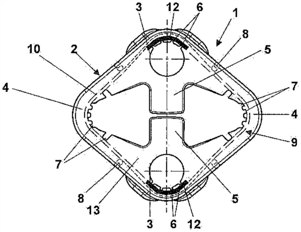
[0026] refer to Figure 1-Figure 5 , this embodiment proposes an elastic lug, including a molded body 2 and a belt ring 9, wherein:
[0027] The shaped body 2 is made of elastic material 13, the shaped body 2 comprises a base body with a rhomboid structure, in two opposite sides of the rhombic base body, a bearing structure 3 is formed by accommodating support pins or other elastic connecting elements, the support pins or other The elastic connecting elements are elastically supported by each other through elastic lugs 1 . There is a space between the two bearing structures 3, and the middle part of the bearing structure 3 is provided with a buffer block 5 extending toward the direction of the other bearing structure 3, and the two sides of the bearing structure 3 respectively extend along the direction of the other two sides of the rhombus base to form elastic arms 4 and the two elastic arms 4 of the bearing structure 3 are integrally connected with the two elastic arms 4 of...
Embodiment 2
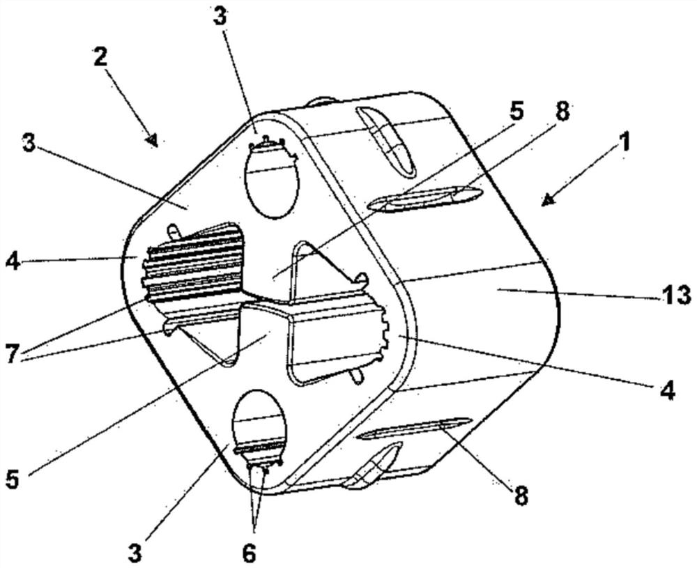
[0035] refer to Figure 6 , Figure 7 The difference between the elastic lug 1 proposed in this embodiment and the first embodiment is that in this embodiment, the connection part 12 is arranged at the outer circumference 15 of the belt ring 9 and embedded in the area of the elastic arm 4 . The two connecting parts 12 respectively abut against the corresponding outer circumference 15 of the belt loop 9 around the center of the lug 9 in the same direction of rotation; On the outer circumference 15 , the two connections 12 can thus abut in a completely symmetrical manner against the belt ring 9 in the bending region of the elastic arm 4 and they can both point obliquely away from the bearing structure 3 downwards.
[0036] The connecting portion 12 is held during the manufacture of the molded body 2 by the injection molding tool in the region where it joins the flange 8 .
Embodiment 3
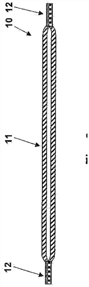
[0038] refer to Figure 8 The difference between the elastic lug 1 proposed in this embodiment and the first embodiment is that in this embodiment, two connecting parts 12 are arranged on the inner circumference of the belt ring 9, and the connecting parts 9 extend toward the buffer block 5 and are embedded in the buffer block 5. In the molding process, the fabric strip 10 is arranged on the mold cores 16, 17 of the injection molding mold, the mold cores 16, 17 have ribs 18, 19 respectively matched with the grooves 6, 7 of the molded body 2; the connecting part 12 The region of the buffer block 5 protrudes from the inner circumference 14 into the molded body 2 and is embedded in the buffer block 5 .
PUM
| Property | Measurement | Unit |
|---|---|---|
| Length | aaaaa | aaaaa |
| Length | aaaaa | aaaaa |
| Length | aaaaa | aaaaa |
Abstract
Description
Claims
Application Information
 - R&D
- Intellectual Property
- Life Sciences
- Materials
- Tech Scout
- Unparalleled Data Quality
- Higher Quality Content
- 60% Fewer Hallucinations
Browse by: Latest US Patents, China's latest patents, Technical Efficacy Thesaurus, Application Domain, Technology Topic, Popular Technical Reports.
© 2025 PatSnap. All rights reserved.Legal|Privacy policy|Modern Slavery Act Transparency Statement|Sitemap|About US| Contact US: help@patsnap.com