Supercharge Your Innovation With Domain-Expert AI Agents!

Heat energy circulation baking device for electronic components

A technology for electronic components and baking devices, which is applied in the directions of drying, drying machine, and drying gas arrangement, and can solve the problems of inability to ensure the movement efficiency of clamping parts, low clamping efficiency of electronic components, and low drying efficiency of devices. and other problems, to achieve the effect of saving labor costs, improving work efficiency, and improving drying efficiency

Inactive Publication Date: 2021-03-02
上海奇月光电科技有限公司
View PDF10 Cites 0 Cited by
  • Summary
  • Abstract
  • Description
  • Claims
  • Application Information

AI Technical Summary

Problems solved by technology

[0003] However, there are still various problems in the use of various thermal energy circulation baking devices for electronic components on the market, and none of them solves the problem that the existing devices cannot hold multiple sets of electronic components for drying at the same time. When clamping multiple sets of electronic components, the movement efficiency of the clamping parts cannot be guaranteed, which makes the drying efficiency of the device low and the clamping efficiency of the device to electronic components is low. For this reason, we propose a thermal energy cycle for electronic components Roasting device

Method used


Image

  • Heat energy circulation baking device for electronic components
  • Heat energy circulation baking device for electronic components
  • Heat energy circulation baking device for electronic components

Examples


Embodiment Construction

[0022]In order to make the technical means, creative features, objectives and effects of the present invention easy to understand, the following further describes the present invention in conjunction with specific embodiments. However, the following embodiments are only preferred embodiments of the present invention, and not all of them. Based on the examples in the implementation manners, other examples obtained by those skilled in the art without creative work shall fall within the protection scope of the present invention. The experimental methods in the following examples are conventional methods unless otherwise specified. The materials and reagents used in the following examples can be obtained from commercial sources unless otherwise specified.

[0023]Example:

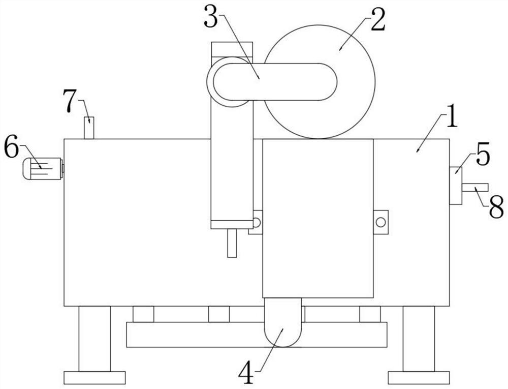
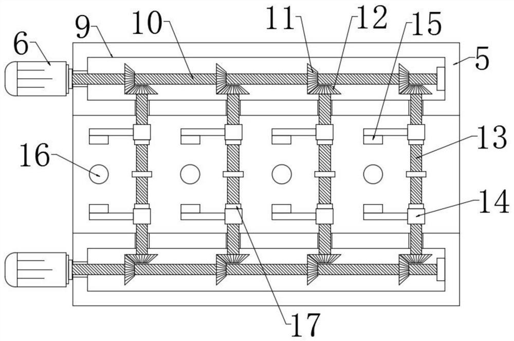
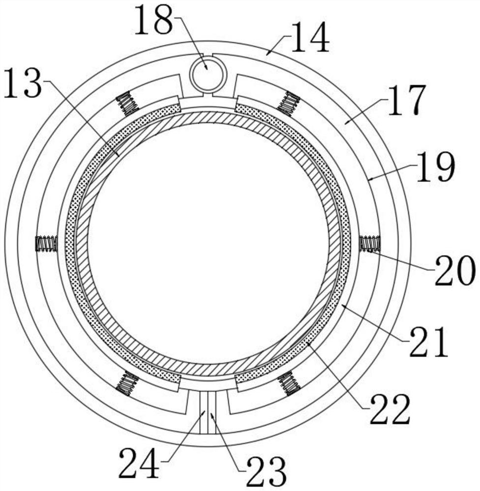
[0024]Such asFigure 1-Figure 3As shown, a thermal energy circulating baking device for electronic components includes a drying box 1, an electric fan 2, a return air duct 3, and a supply air duct 4. The feature is that the...


PUM


Abstract

The invention discloses a heat energy circulation baking device for electronic components. The heat energy circulation baking device comprises a drying box, an electric heating fan, an air return pipeand an air supply pipe, and is characterized in that U-shaped containing plates are limited and slide in the drying box; grooves are symmetrically formed in the top surfaces of the U-shaped containing plates; motors are symmetrically arranged on one sides of the U-shaped containing plates; the output ends of the motors are in transmission connection with first lead screws; the first lead screws extend into the grooves; bearings are arranged at the rotating connection positions of the first lead screws and the U-shaped containing plates; the surfaces of the first lead screws are fixedly sleeved with driving gears at equal intervals; the surfaces of one sides of the driving gears are connected with drive gears in an engaged mode; second lead screws are fixedly arranged in the drive gears ina penetrating mode; the second lead screws are arranged on the surfaces of the U-shaped containing plates in a penetrating mode; the second lead screws are rotationally connected with the U-shaped containing plates; the surfaces of the second lead screws are movably sleeved with threaded sleeves; and clamping plates are fixed to the surfaces of one sides of the threaded sleeves.

Description

Technical field[0001]The invention relates to the technical field of electronic component processing, in particular to a thermal energy cycle baking device for electronic components.Background technique[0002]The development of modern electronics industry is inseparable from electronic components. When processing and producing some solid electronic products, it is necessary to go through the processes of cleaning, soaking, rinsing, dust removal, etc., and then baking and drying the electronic components through the corresponding device to achieve dehydration and drying, and the thermal energy cycle of the electronic components is used for drying. The roasting device can effectively save energy.[0003]However, there are still various problems in the use of various electronic component thermal cycle baking devices on the market, which have not solved the existing device’s inability to clamp multiple sets of electronic components for drying at the same time. When clamping multiple sets o...

Claims


Application Information

Patent Timeline
IPC IPC(8): F26B11/00F26B21/00F26B25/02F16F15/067B08B1/00
CPCF26B11/00F26B21/001F26B25/02F16F15/067B08B1/12
Inventor 李磊李祥
Owner 上海奇月光电科技有限公司
Features
  • R&D
  • Intellectual Property
  • Life Sciences
  • Materials
  • Tech Scout
  • Unparalleled Data Quality
  • Higher Quality Content
  • 60% Fewer Hallucinations
Learn More