System for controlling new energy vehicle to drive into charging parking space

A technology for new energy vehicles and parking spaces, which is applied in traffic control systems, traffic control systems for road vehicles, and directions indicating various open spaces in parking lots. It can solve problems such as prolonged charging time, vehicle congestion, and increased difficulty in thermal management systems. Achieve the effect of guaranteeing no loss, reducing damage, and easy inspection

Inactive Publication Date: 2021-03-02
WENCHENG POWER SUPPLY CO OF STATE GRID ZHEJIANG ELECTRIC POWER CO +2
View PDF9 Cites 0 Cited by
  • Summary
  • Abstract
  • Description
  • Claims
  • Application Information

AI Technical Summary

Problems solved by technology

[0002] With the wave of development in the field of new energy vehicles, the development momentum of new energy vehicles is strong and the scope is widespread. However, the pain points of new energy vehicles are that the cruising range of new energy vehicles is required to be more than 450km (with cross-province capability), and the cost of batteries is too high, which leads to excessive vehicle costs. High, the ensuing problem is that the battery power increases, the charging time increases, and the thermal management system becomes more difficult. Therefore, the application of charging parking spaces is becoming more and more extensive. It is necessary to input vehicle information, and the existing input information is manually operated, resulting in low overall input efficiency. Secondly, there is no device installed in front of the charging parking space to control the new energy vehicles entering the charging parking space, which will easily cause congestion of vehicles and is not conducive to charging.

Method used


Image

  • System for controlling new energy vehicle to drive into charging parking space
  • System for controlling new energy vehicle to drive into charging parking space
  • System for controlling new energy vehicle to drive into charging parking space

Examples


Embodiment Construction

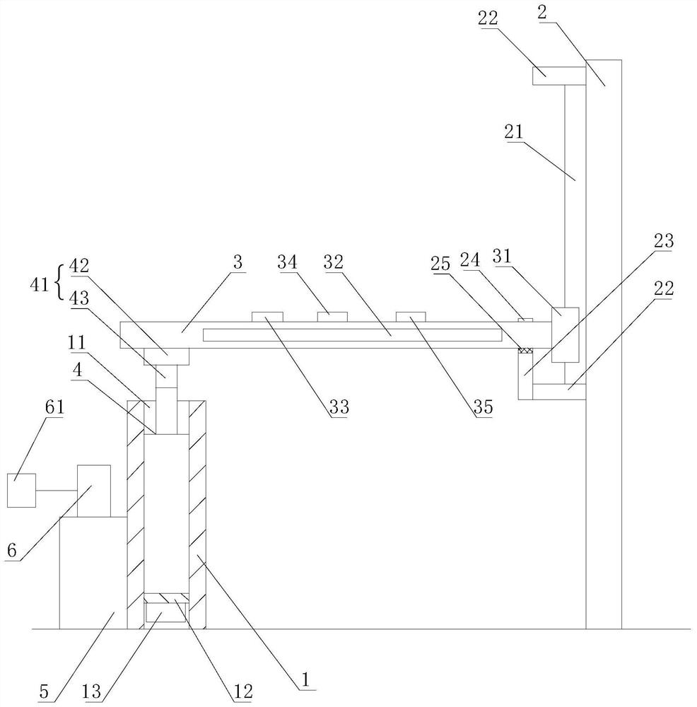
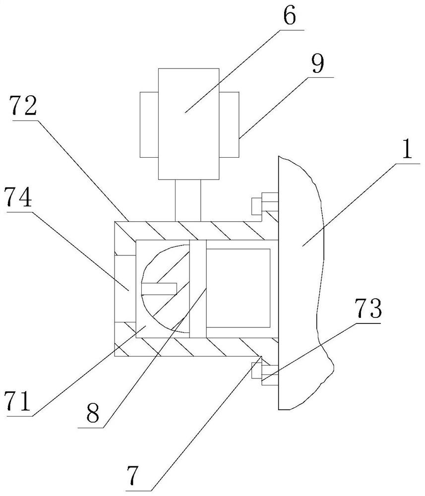
[0023] Such as figure 1 , figure 2 , image 3 , Figure 4 As shown, a system for controlling new energy vehicles to drive into the charging parking space is applied to the charging parking space, including a left column 1, a right column 2 and a railing 3. The left column 1 and the right column 2 are respectively arranged at the entrance of the charging parking space. Both sides, described left column 1 is provided with vertical through-hole 11, is provided with the push rod motor 4 that links to each other with one end of railing 3 in described vertical through-hole 11, and the other end of described railing 3 is movably connected on the right side. On the column 2, the left column 1 is also provided with a detection device 5 that drives the push rod motor 4 to rise and fall, and the detection device 5 is also provided with a camera 6 for identifying vehicle information, and the camera 6 is connected to a PC Machine 61.

[0024] By setting the railing 3 between the left ...


PUM


Abstract

The invention relates to a system for controlling a new energy vehicle to drive into a charging parking space. The system comprises a left stand column, a right stand column and a handrail, a verticalthrough hole is formed in the left stand column, a push rod motor is arranged in the vertical through hole, a detection device is also arranged on the left stand column, a camera is also arranged onthe detection device, and a PC is connected to the camera; the system has the advantages that: the handrail is arranged between the left stand column and the right stand column, and the left stand column and the right stand column are respectively arranged at two sides of the entrance of the charging parking space, so that the handrail arranged on the left stand column and the right stand column can play a certain blocking role at the entrance of the charging parking space, and when a vehicle enters the charging parking space, the vehicle can be prevented from entering by mistake; congestion of vehicles at the charging space is avoided and charging work is down in order. The vehicle information can be stored by the camera, so that the subsequent consultation is facilitated, and the information shot by the camera can be stored by the PC in real time, thereby ensuring that the information is not lost.

Description

technical field [0001] The invention relates to a system for controlling a new energy vehicle to drive into a charging parking space. Background technique [0002] With the wave of development in the field of new energy vehicles, the development momentum of new energy vehicles is strong and the scope is widespread. However, the pain points of new energy vehicles are that the cruising range of new energy vehicles is required to be more than 450km (with cross-province capability), and the cost of batteries is too high, which leads to excessive vehicle costs. High, the ensuing problem is that the battery power increases, the charging time increases, and the thermal management system becomes more difficult. Therefore, the application of charging parking spaces is becoming more and more extensive, and when existing new energy vehicles drive into charging parking spaces, It is necessary to input vehicle information, but the existing input information is manually operated, resultin...

Claims


Application Information

Patent Timeline
Patent Type & Authority Applications(China)
IPC IPC(8): G07C9/20G08G1/14E01F13/04
CPCG07C9/20G08G1/149E01F13/04
Inventor 梅慧敏胡碎磊吴立省金宏杰陈丽红李从兵梅建敏郭江
Owner WENCHENG POWER SUPPLY CO OF STATE GRID ZHEJIANG ELECTRIC POWER CO
Why Eureka
Try Eureka