Kitchen lampblack collecting and purifying device for tourist hotels

A purification device and absorption device technology, applied in the direction of oil fume removal, chemical instruments and methods, cleaning hollow objects, etc., can solve the problems of time-consuming and labor-intensive maintenance and cleaning, inability to separate oil stains, troublesome filter element cleaning, etc., to achieve low cost of use, Efficient degreasing operation, good effect

Inactive Publication Date: 2021-03-05
江西环境工程职业学院
View PDF9 Cites 1 Cited by
  • Summary
  • Abstract
  • Description
  • Claims
  • Application Information

AI Technical Summary

Problems solved by technology

[0003] The existing oil fume collection and purification device in the tourist hotel kitchen cannot separate the oil stains well; the oil stains attached to the inner wall of the pipeline can only be cleaned by disassembling the device, and maintenance and cleaning are time-consuming and laborious; cleaning through the filter element is expensive, and the cleaning of the filter element Trouble, not suitable for promotional use

Method used


Image

  • Kitchen lampblack collecting and purifying device for tourist hotels
  • Kitchen lampblack collecting and purifying device for tourist hotels
  • Kitchen lampblack collecting and purifying device for tourist hotels

Examples


Embodiment 1

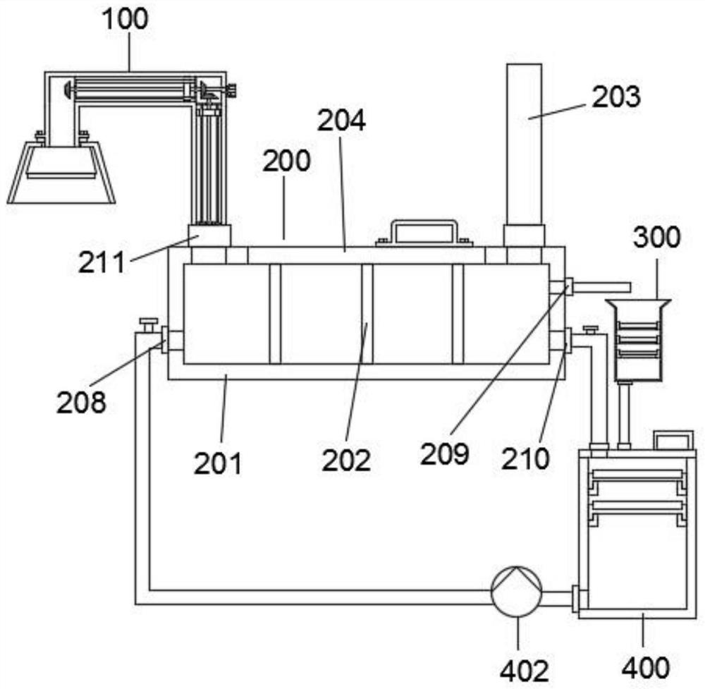
[0034] Refer to the attached Figure 1-6 , a kitchen oil fume collection and purification device of a tourist hotel in this embodiment, comprising an absorption device 100, a treatment device 200, an oil removal device 300 and a circulation device 400;

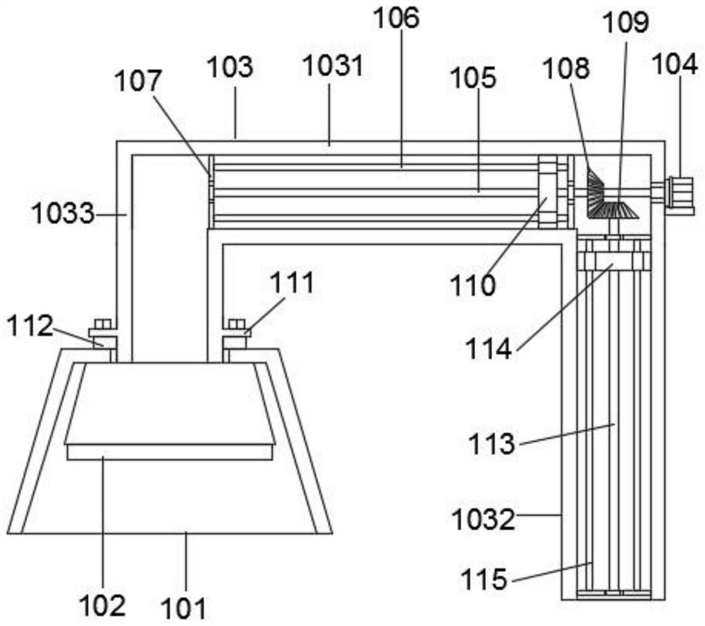
[0035]Further, the absorption device 100 includes a trapezoidal cover 101, a blower fan 102, a U-shaped collection pipe 103, a servo motor 104, a screw rod one 105, an anti-rotation rod one 106, a support plate 107, a driving truncated conical gear 108, and a driven truncated conical gear 109, scraper one 110, installation disc 111, sealing ring 112, screw mandrel two 113, scraper two 114, anti-rotation rod two 115, horizontal tube 1031, vertical tube two 1032 and vertical tube one 1033, specifically, the The fan 102 is fixedly installed on the top of the inner cavity of the trapezoidal cover 101, and the inner wall of the top of the trapezoidal cover 101 is plugged with a U-shaped collection pipe 103. The collection pipe 103 ...

Embodiment 2

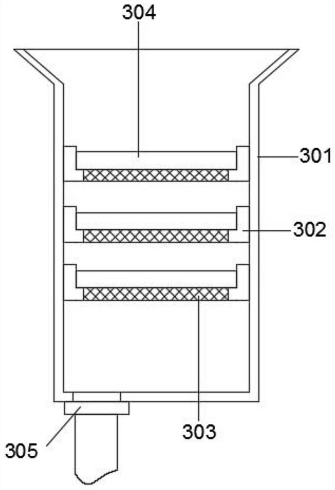
[0041] Refer to the attached Figure 7-8 , the difference from Embodiment 1 is that: the processing device 200 also includes a clamping plate 206 and a layered plate 207, the clamping plate 206 is fixed on the inner wall of the processing box 201 by bolts, the clamping The inner wall of the plate 206 is clamped to the layered plate 207; the function of the layered plate 207 is to block the oil stains on the water surface on the water outlet 210, so that the oil stains flow into the oil removal cylinder 301 through the oil outlet 209;

[0042] The specific implementation scenarios are:

[0043] Compared with Embodiment 1, when using the present invention, start the fan 102 and the water pump 402, the smoke in the kitchen enters the U-shaped collection pipe 103 under the suction of the fan 102, and then enters the treatment box 201 through the air inlet 211 Because three groups of staggered partitions 202 are set in the treatment box 201, the flue gas flows along with the water...


PUM


Abstract

The invention belongs to the technical field of kitchen oil fume treatment, and particularly relates to a kitchen lampblack collecting and purifying device for tourist hotels. The device comprises anabsorption device, a treatment device, an oil removing device and a circulating device, the bottom of the right end of the absorption device is fixedly connected with the treatment device, and the oilremoving device is arranged on the right side of the treatment device; and the circulating device is arranged below the oil removing device, the absorption device comprises a trapezidal cover, and afan is fixedly installed at the top of the inner cavity of the trapezidal cover. The kitchen lampblack collecting and purifying device has the beneficial effects that three groups of staggered partition plates enable flue gas to flow along with water according to an S-shaped path, the speed of the flue gas and the water flowing to the right end of the treatment box is reduced, oil stains have sufficient time to float on the water surface, the oil-water separation effect is better, automatic cleaning of a U-shaped collecting pipeline is achieved, the kitchen lampblack collecting and purifying device does not need to be dismounted, and maintenance and cleaning become very convenient.

Description

technical field [0001] The invention relates to the technical field of kitchen fume treatment, in particular to a device for collecting and purifying kitchen fume in a tourist hotel. Background technique [0002] The oil fume purification device is used in restaurant kitchens and is installed on the exhaust duct to purify the oil fumes generated during stove cooking and prevent harmful oil fumes from being directly discharged into the air to pollute the environment. Common treatment processes include filtration, cooling, electrostatic, water mist, and chemical methods. [0003] The existing oil fume collection and purification device in the tourist hotel kitchen cannot separate the oil stains well; the oil stains attached to the inner wall of the pipeline can only be cleaned by disassembling the device, and maintenance and cleaning are time-consuming and laborious; cleaning through the filter element is expensive, and the cleaning of the filter element Trouble, not suitable...

Claims


Application Information

Patent Timeline
IPC IPC(8): B01D47/02B01D29/56B01D29/96B08B9/051F24C15/20
CPCB01D29/56B01D29/96B01D47/02B08B9/051F24C15/2035
Inventor 罗敏
Owner 江西环境工程职业学院
Why Eureka
Try Eureka