
Device and method for fast positioning and pasting of fiber grating sensor

A fiber grating and sticking device technology, which is applied in the direction of coating liquid on the surface, connecting components, coatings, etc., can solve the problems affecting the use of fiber grating strain/stress sensors, poor positioning accuracy, slow sticking speed, etc. Improve the paste precision and paste quality, easy operation, reliable work effect

Active Publication Date: 2021-10-01
QINGDAO DMAR OCEAN ENG
View PDF0 Cites 0 Cited by
  • Summary
  • Abstract
  • Description
  • Claims
  • Application Information

AI Technical Summary

Problems solved by technology

At present, there is no special device for pasting this type of fiber grating sensor, which requires manual positioning and pasting. The positioning accuracy is poor, the pasting speed is slow, the efficiency is low, and the pasting quality is poor, which greatly affects the use of unpackaged fiber grating multi-measuring point strain / stress sensors.

Method used


Image

  • Device and method for fast positioning and pasting of fiber grating sensor
  • Device and method for fast positioning and pasting of fiber grating sensor
  • Device and method for fast positioning and pasting of fiber grating sensor

Examples


Embodiment 1

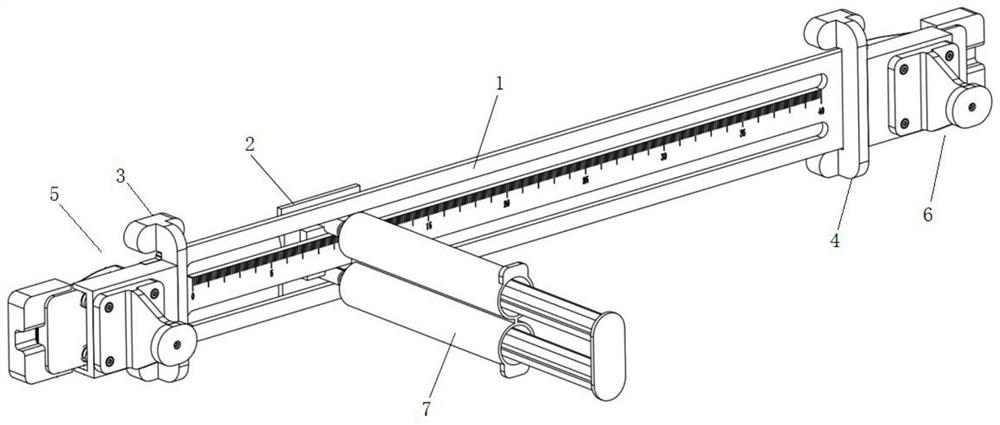
[0050] This embodiment provides a fiber grating sensor fast positioning paste device, such as figure 1 As shown, it includes: a guide scale 1, a moving glue head 2, a first fixing buckle 3, a second fixing buckle 4, a first support member 5 and a second support member 6;

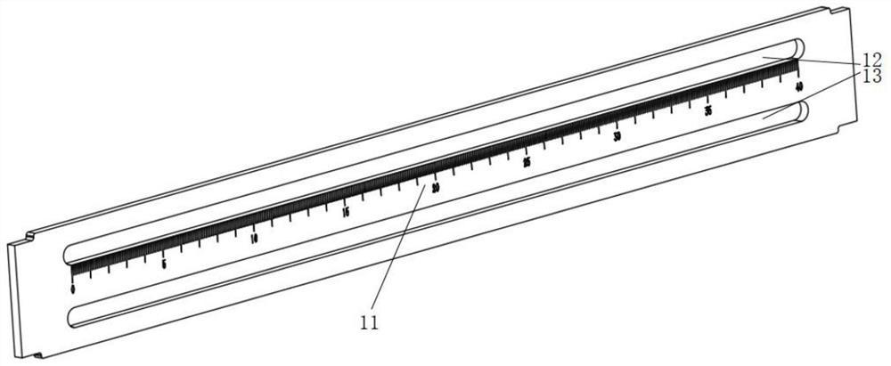
[0051] The guide scale 1 includes a scale line, which is used to locate the sticking position of the fiber grating sensor;

[0052] The mobile gluing head 2 is movably connected with the guide scale 1, and is used to move along the scale line so that the adhesive material is coated on the sticking position on the fiber grating sensor, so that the fiber grating sensor is pasted to the surface of the measured structure;

[0053] The first fixing buckle 3 and the second fixing buckle 4 are buckled on the two side surfaces of the guide scale 1 respectively, and are used to fix the guide scale 1 to the surface of the structure to be measured;

[0054] The first supporting part 5 and the second supporting part 6 ...

Embodiment 2

[0077] This embodiment provides a fast positioning and pasting method for a fiber grating sensor, which can be applied to the fast positioning and pasting device for a fiber grating sensor in embodiment 1, such as Figure 10 As shown, the method includes the following steps:

[0078] S1. Fix the fast positioning and sticking device of the fiber grating sensor to the surface of the structure under test through the first fixing buckle and the second fixing buckle, so that the mobile glue applicator is placed near the position to be pasted;

[0079] S2. Pull the lifting handles of the first supporting part and the second supporting part, and lift the outer pressing parts of the two;

[0080] S3. Pass the fiber grating sensor through the gap between the inner pressing piece and the outer pressing piece respectively, so that the position to be pasted of the fiber grating sensor is aligned with the position to be pasted on the surface of the measured structure;

[0081] S4. Loosen ...


PUM


Abstract

The invention discloses a fiber grating sensor fast positioning and pasting device and method, and relates to the technical field of fiber optic sensor installation. The ruler is movable and connected, and is used to move along the scale line so that the viscose material is coated on the sticking position on the fiber grating sensor; the first fixed buckle and the second fixed buckle are buckled on the two sides of the guide scale respectively, and are used to The guide scale is fixed on the surface of the structure to be measured; and the first supporting part and the second supporting part are respectively connected to the two ends of the guide scale, and are used to fix the two ends of the fiber grating sensor, so that the fiber grating sensor moves along the guide scale. The direction of the scale line is arranged straight and close to the surface of the structure under test. The invention has the advantages of fast pasting speed, high precision and good quality, reliable work and convenient operation.

Description

technical field [0001] The invention relates to the technical field of optical fiber sensor installation, in particular to a fast positioning and pasting device and method for an optical fiber grating sensor. Background technique [0002] The unpackaged fiber grating multi-measuring point strain / stress sensor has flexible layout and high cost performance, and is widely used in the monitoring of physical quantities such as stress, strain and temperature of engineering structures. Compared with conventional resistive strain gauges, the fiber grating sensor has the advantages of strong anti-electromagnetic interference and long-term stability, especially suitable for long-term monitoring of structural strain. When measuring strain, it is necessary to paste the fiber grating sensor on the structure under test, and the fiber grating sensor is a cylinder with a small diameter (micron scale). When pasting, there is a line contact between the sensor and the structure under test, whi...

Claims


Application Information

Patent Timeline
Patent Type & Authority Patents(China)
IPC IPC(8): B05C5/02B05C11/10B05D1/28F16B11/00
CPCB05C5/0212B05C11/1005B05D1/28F16B11/006
Inventor 康永田李民刚王昆李晓东张大刚王云飞
Owner QINGDAO DMAR OCEAN ENG
Learn More