Double-station tool for machining outer edges of brakes and machining method of double-station tool

A dual-station and brake technology, which is applied to positioning devices, metal processing equipment, metal processing machinery parts, etc., can solve problems such as low efficiency, uneven processing of the outer edge of the brake, and affecting the health of workers, so as to save time.

Pending Publication Date: 2021-03-05
青岛海通制动器有限公司
View PDF0 Cites 2 Cited by
  • Summary
  • Abstract
  • Description
  • Claims
  • Application Information

AI Technical Summary

Problems solved by technology

The existing processing tooling for the outer edge of the brake (brake pad position) locks the two brakes to the cylindrical boss through the locking rod, so that the two brakes are surrounded by the cylindrical boss, and the tool holder is vertically lowered and close to it. The outer edge of the brake in the embracing state, the circular boss starts to drive the brake to rotate, the outer edge of the brake contacts the tool on the tool holder, and the outer edge of the brake is cut off; in this processing method, either the length of the tool on the tool holder is greater than that of the brake Length, that is, cutting to all the parts of the brake that are in contact with the tool at one time, which brings about the problem of large resistance, resulting in a high rate of tool damage. If the tool is reduced, half of the brake will be processed at a time. The two brakes are disassembled, and the cylindrical boss is turned upside down for secondary processing, resulting in uneven processing of the outer edge of the brake and low efficiency. Moreover, at present, they are all single-station clamping, and it is necessary to wait for the processing to be completed. Processing after re-clamping
In addition, the milling waste flying during the machining process affects the health of workers, and also affects the service life of the electrical system, pneumatic system, and hydraulic system that are matched with the tooling.

Method used


Image

  • Double-station tool for machining outer edges of brakes and machining method of double-station tool
  • Double-station tool for machining outer edges of brakes and machining method of double-station tool
  • Double-station tool for machining outer edges of brakes and machining method of double-station tool

Examples


Embodiment Construction

[0026] The following will clearly and completely describe the technical solutions in the embodiments of the present invention with reference to the accompanying drawings in the embodiments of the present invention. Obviously, the described embodiments are only some, not all, embodiments of the present invention. Based on the embodiments of the present invention, all other embodiments obtained by persons of ordinary skill in the art without making creative efforts belong to the protection scope of the present invention.

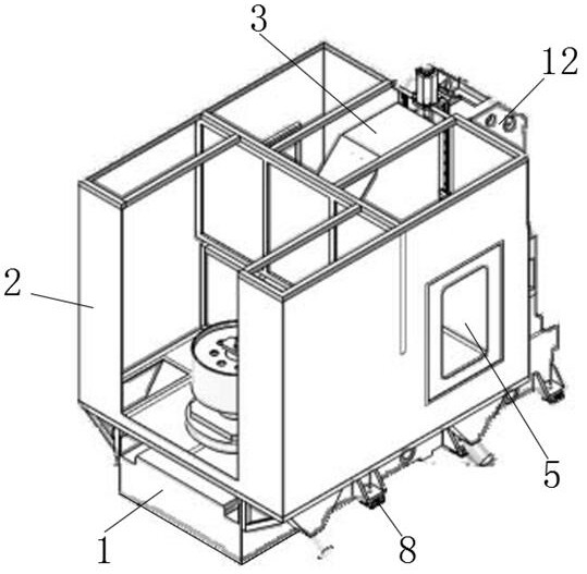
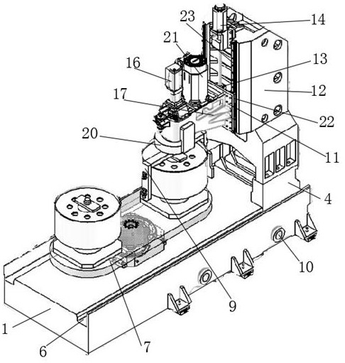
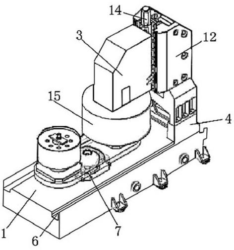
[0027] see Figure 1-4 , the present invention provides a technical solution: a double-station tooling for processing the outer edge of the brake and its processing method, including a body 1, the bottom of the body 1 is fixedly connected with a connecting flange 8, and both side walls of the body 1 are fixedly connected with A plurality of chip removal pipes 10, a shell 2 is fixedly connected around the top of the body 1, a double-station cam workbench 7 is f...


PUM


Abstract

The invention provides a double-station tool for machining the outer edges of brakes. The double-station tool comprises a machine body, wherein a connecting flange is fixedly connected to the bottom of the machine body; a plurality of chip removal pipes are fixedly connected to the two side walls of the machine body; a shell is fixedly connected to the periphery of the top of the machine body; a double-station cam workbench is fixedly connected to the front end of the upper surface of the machine body; sliding rails are arranged on the two sides of the upper surface of the machine body; a linear drive frame is arranged at the rear end of the upper surface of the machine body and is in sliding clamping connection with the sliding rails; and an air cylinder support is fixedly connected to the top of the linear drive frame. According to the double-station tool for machining the outer edges of the brakes and a machining method of the double-station tool, the two brakes are assembled on thedouble-station cam workbench, one brake is used for machining, and the workpiece installing time is saved; and the linear drive frame works to drive the air cylinder support to push, the linear driveframe slides on the sliding rails, a cross beam is driven to move, the effect of better collecting waste chips generated during machining is achieved, the machining efficiency is greatly improved, and workpiece installing and replacing are more user-friendly.

Description

technical field [0001] The invention relates to the field of brake processing, in particular to a double-station tool for processing the outer edge of a brake and a processing method thereof. Background technique [0002] A brake is a device that has the functions of slowing down, stopping or keeping a moving part (such as a car) in a stopped state. It is a mechanical part that stops or slows down a moving part in a machine. Commonly known as brakes, brakes. The existing processing tooling for the outer edge of the brake (brake pad position) locks the two brakes to the cylindrical boss through the locking rod, so that the two brakes are surrounded by the cylindrical boss, and the tool holder is vertically lowered and close to it. The outer edge of the brake in the embracing state, the circular boss starts to drive the brake to rotate, the outer edge of the brake contacts the tool on the tool holder, and the outer edge of the brake is cut off; in this processing method, ei...

Claims


Application Information

Patent Timeline
Patent Type & Authority Applications(China)
IPC IPC(8): B23D79/00B23Q3/06B23Q5/28B23Q11/00B23Q11/08
CPCB23D79/00B23Q3/06B23Q5/28B23Q11/0046B23Q11/08
Inventor 佟新杰刘啸尘王太星李冰
Owner 青岛海通制动器有限公司
Why Eureka
Try Eureka