Energy-saving building outdoor floor installation structure and installation method thereof

A technology for installing structures and outer floors, which is applied to building structures, buildings, and partial raised floors, etc., can solve the problems of unguaranteed waterproofness, damage to the waterproof layer, and high frequency of repairs, etc., to achieve simple structure and extended Effect of service life and cost reduction

Active Publication Date: 2021-03-05
CECEP (JIASHAN) ENVIRONMENTAL PROTECTION TECH PARK DEV CO LTD +1
View PDF6 Cites 0 Cited by
  • Summary
  • Abstract
  • Description
  • Claims
  • Application Information

AI Technical Summary

Problems solved by technology

[0003] The outdoor platform is an inaccessible part of the building. Floor installation is a relatively common decoration method for outdoor platforms. In the prior art, the floor is installed between the ground bolts and the ground, but there are living spaces under the outdoor platform. Space, the installation method of driving the ground bolts will damage the waterproof layer of the outdoor platform. Therefore, when laying the floor, we also need to seal the installation position of the ground bolts
The wear and tear of the outdoor ground is more serious than that of the indoor. Therefore, the frequency of maintenance is higher. For each maintenance, the glued position of the ground bolt needs to be removed. Not to mention the troublesome operation, the water resistance after the repair cannot be guaranteed.

Method used


Image

  • Energy-saving building outdoor floor installation structure and installation method thereof
  • Energy-saving building outdoor floor installation structure and installation method thereof
  • Energy-saving building outdoor floor installation structure and installation method thereof

Examples


Embodiment 1

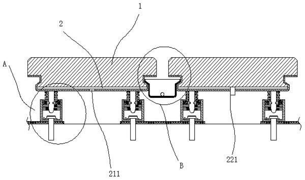
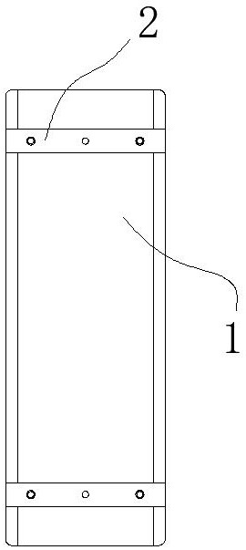
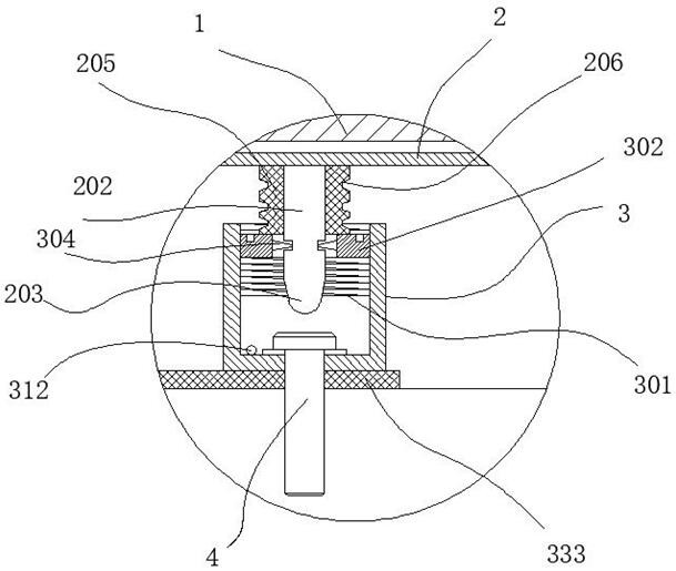
[0041]An energy-saving building outdoor floor installation structure, including a floor 1 installed outdoors, and a plurality of brackets 2 matching the floor 1, half dovetail grooves 101 are turned on both sides of the bottom of the floor 1, the The left and right ends of the bracket 2 are bent upwards to form a support part 201 that fits the half dovetail groove 101. The support part 201 is in a half dovetail shape. When the support part 201 fits the half dovetail groove 101, the A gap is formed between the lower end surface of the floor 1 and the upper end surface of the support 2, and two insertion shafts 202 are arranged at the bottom of each support 2, and the lower ends of the insertion shafts 202 are processed to form a bullet-shaped guide portion 203, the base 3 corresponding to the insertion shaft 202 is installed on the carrier, the base 3 is a hollow structure, its upper end has an opening, the inside of the base 3 is processed with a threaded part 301, and an inner...

Embodiment 2

[0043] A collection tank 5 for collecting garbage is installed between the left and right adjacent floors 1, and a dovetail groove is formed between the left and right adjacent supports 2 through the support part 201, and the collection tank 5 is dovetail-shaped. The collection tank 5 is supported between the supporting parts 201 on both sides, and the collection tank 5 can slide back and forth, and the opening width of the collection tank 5 is larger than the seam formed between the left and right two floors 1; The front end of the collection tank 5 is provided with a drainage hole 501 . When we are doing outdoor activities, we will find that a lot of sundries, particles, etc. have accumulated in the gap formed by the adjacent floor 1, which greatly affects the appearance, and it is very difficult to clean up, and it will be damaged if you are not careful. Impurities, etc. are fiddled to the bottom of the floor, making it more difficult to clean. Especially the peel and the ...

Embodiment 3

[0046] The bottom of the bracket 2 is provided with a drain hole 211 vertically penetrating through it. The drain hole 211 is a threaded hole, and a fixing screw 221 is detachably fitted through the drain hole 211. Floor 1, at this time, the support 2 and the floor 1 are fixed; if we use the support 2 with a smaller longitudinal width, the floor can be reinforced with fixing screws 221, if we use the support 2 with a larger longitudinal width , then the hydrophobic capacity of bracket 2 will decrease. At this time, we can remove the fixing screws to facilitate the drainage of bracket 2. At the same time, there is a gap between bracket 2 and floor 1 after assembly, so the bottom of floor 1 can be avoided for a long time. , indirectly improving the durability of the floor 1.


PUM


Abstract

The invention discloses an energy-saving building outdoor floor installation structure and an installation method thereof. The energy-saving building outdoor floor installation structure comprises a floor installed outdoors and a plurality of supports matched with the floor; semi-dovetail grooves are formed in two side edges of the bottom of the floor in a turning mode; the left ends and the rightends of the supports are bent upwards to form supporting parts matched with the semi-dovetail grooves; the supporting parts are in a semi-dovetail shape; when the supporting parts are matched with the semi-dovetail grooves, the lower end face of the floor is separated from the upper end faces of the supports to form a gap; and two inserting shafts are arranged at the bottom of each support. In the product, fixation between the floor and the ground is achieved through cooperation of the inserting shafts and inner plate pieces, and when a damaged floor needs to be maintained, if the floor has afront-back sliding space, the floor can be directly taken out for maintenance after sliding front and back.

Description

technical field [0001] The invention relates to an installation structure of an energy-saving building outdoor floor and an installation method thereof. Background technique [0002] Energy-saving buildings refer to the low-energy buildings designed after the study of building planning zoning, groups and monomers, building orientation, spacing, solar radiation, wind direction and external space environment in accordance with the basic methods of climate design and energy conservation. [0003] The outdoor platform is an inaccessible part of the building. Floor installation is a relatively common decoration method for outdoor platforms. In the prior art, the floor is installed between the ground bolts and the ground, but there are living spaces under the outdoor platform. Space, the installation method of driving ground bolts will damage the waterproof layer of the outdoor platform. Therefore, when laying the floor, we also need to seal the installation position of the ground...

Claims


Application Information

Patent Timeline
Patent Type & Authority Applications(China)
IPC IPC(8): E04F15/02E04F15/024
CPCE04F15/02033E04F15/02016E04F15/02044E04F15/02183E04F15/02411E04F15/02435E04F15/02452E04F15/02458E04F2015/02105
Inventor 周建旺蒋雪峰叶汀沈哲艺
Owner CECEP (JIASHAN) ENVIRONMENTAL PROTECTION TECH PARK DEV CO LTD
Why Eureka
Try Eureka