Double-cavity injection device

An injection device and infusion technology, which is applied in the field of medical devices, can solve the problems of heavy burden on patients, high medical cost, and high price of automatic injectors, and achieve the effect of reducing medical cost, reducing the overall price, and reducing the burden on patients

Pending Publication Date: 2021-03-09
李荣毓
View PDF1 Cites 0 Cited by
  • Summary
  • Abstract
  • Description
  • Claims
  • Application Information

AI Technical Summary

Problems solved by technology

[0006] The technical problem to be solved by the present invention is: in order to overcome the problem that two automatic injectors are fixedly arranged on the same housing in the prior art, the two automatic injectors include two micro motors, the price of the micro motors is relatively high, and the overall price of the automatic injector is relatively high. high, leading to high medical costs and heavy burden on patients, a dual-chamber injection device is provided

Method used


Image

  • Double-cavity injection device
  • Double-cavity injection device
  • Double-cavity injection device

Examples


Embodiment 1

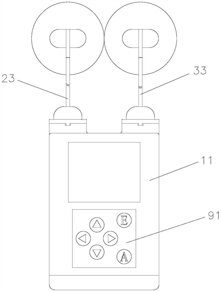
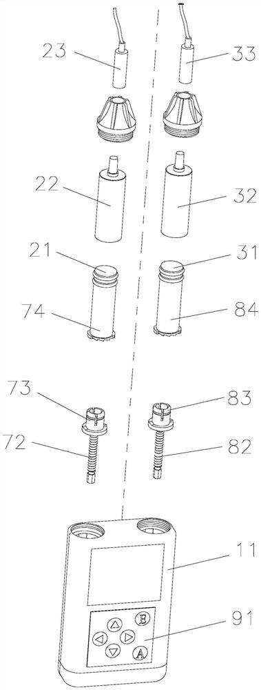
[0048] Such as Figure 1-Figure 3 The shown dual-chamber injection device includes a housing 11, a first infusion mechanism and a second infusion mechanism are arranged in the housing 11, the first infusion mechanism includes a first piston 21, a first infusion cylinder 22 and the first infusion line 23, the first infusion tube 22 is fixedly installed in the housing 11, the first infusion line 23 is detachably installed on the first infusion tube 22, and the detachable connection here can be threaded connection, The connection methods such as card connection are convenient for disassembly; the first piston 21 is slidably arranged in the first infusion tube 22; the second infusion mechanism includes the second piston 31, the second infusion tube 32 and the second infusion line 33, and the The second infusion tube 32 is fixedly installed in the housing 11, and the second infusion line 33 is detachably installed on the second infusion tube 32. The detachable connection here can b...

Embodiment 2

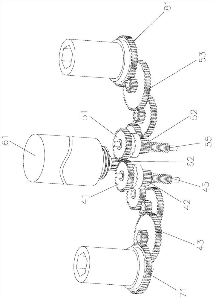
[0061] In order to achieve automatic control, such as Figure 4-Figure 6 The difference between the illustrated embodiment 2 and the embodiment 1 is only that: both the first clutch mechanism and the second clutch mechanism are electromagnetic clutch mechanisms;

[0062] The first clutch mechanism includes a first driven gear 41, a first clutch gear 42, a first transmission gear 43, and a first electromagnet 44. The first driven gear 41 is rotatably installed in the housing 11 and connected to the rotating mechanism in transmission. The first electromagnet 44 is fixedly installed in the housing 11, the first clutch gear 42 slides and rotates and is arranged between the first driven gear 41 and the first electromagnet 44, the first driven gear 41 and the first clutch gear 42 The two opposite surfaces are provided with meshing teeth that can mesh with each other. A first reset assembly is arranged between the first electromagnet 44 and the first clutch gear 42. The first reset a...

Embodiment 3

[0068] In order to use the present invention to realize the injection function, such as Figure 7 with Figure 8 The difference between the illustrated embodiment 3 and the embodiment 1 is that the first infusion mechanism also includes a first infusion tube 22 and a first injection needle 24, and the first infusion tube 22 is fixedly installed in the housing 11 , the first injection needle 24 is detachably installed on the first infusion tube 22, and the detachable connection here can be a connection method such as threaded connection or clamping that is convenient for detachment; the first piston 21 is slidably arranged on the first infusion tube 22 Inside, the second infusion mechanism also includes a second infusion tube 32 and a second injection needle 34, the second infusion tube 32 is fixedly installed in the housing 11, and the second injection needle 34 is detachably installed in the second infusion tube 32 , the detachable connection here may be a threaded connectio...


PUM


Abstract

The invention relates to a double-cavity injection device. The device comprises a first driving mechanism, a second driving mechanism, a rotating mechanism, a first clutch mechanism and a second clutch mechanism, the first clutch mechanism is connected with the rotating mechanism and the first driving mechanism and the second clutch mechanism is connected with the rotating mechanism and the seconddriving mechanism; when the first clutch mechanism works, power of the rotating mechanism can be transmitted to the first driving mechanism through the first clutch mechanism, and the second clutch mechanism does not work; and when the second clutch mechanism works, the power of the rotating mechanism can be transmitted to the second driving mechanism through the second clutch mechanism, the first clutch mechanism does not work, and a second infusion mechanism works. According to the double-cavity injection device, a first infusion mechanism and the second infusion mechanism are driven by oneset of rotating mechanism, the first infusion mechanism and the second infusion mechanism do not infuse liquid at the same time, after infusion of the first infusion mechanism is completed, the second infusion mechanism can conduct infusion immediately, a patient does not need to wait, the medical cost is reduced, and the burden of the patient is relieved.

Description

technical field [0001] The invention relates to the technical field of medical instruments, in particular to a double-chamber injection device. Background technique [0002] A syringe is a very common medical device. When using an existing syringe, the needle of the syringe is generally inserted into the medicine bottle manually, and the piston rod is driven by pulling the piston rod, so that the medicine liquid is extracted by using the air pressure difference. Insert the needle into the syringe, then insert the needle into the patient's vein, and then press the piston rod to inject the drug solution into the patient's body. However, when the injection is performed manually, it is easy to cause the injection speed to be too fast due to too much force when pressing, which will impact the patient's venous blood vessels, thereby causing strong discomfort to the patient. [0003] In order to solve the above problems, the Chinese patent No. 201920619597.6 discloses "An Automati...

Claims


Application Information

Patent Timeline
IPC IPC(8): A61M5/20A61M5/19A61M5/31
CPCA61M5/19A61M5/20A61M5/31A61M2005/2006
Inventor 李荣毓
Owner 李荣毓
Why Eureka
Try Eureka