Dust removal device special for resistive load box

A technology of resistive load and ash cleaning device, which is applied in the cleaning method using gas flow, removal of smoke and dust, transportation and packaging, etc., can solve the problems of poor cleaning effect and dust scattering, and achieve the effect of preventing dust scattering and quick cleaning.

Active Publication Date: 2021-03-09
HANGZHOU VOCATIONAL & TECHN COLLEGE
View PDF9 Cites 0 Cited by
  • Summary
  • Abstract
  • Description
  • Claims
  • Application Information

AI Technical Summary

Problems solved by technology

[0003] When the resistance load box is used, it is often necessary to clean the dust inside the load box with the dust removal device. The current dust removal device dedicated to the resistance load box generally has a simple structure, and the dust is blown out from the inside of the load box by a fan, which often causes When the dust is scattered, the existing dust cleaning device dedicated to the resistance load box is not easy to blow out and collect the dust quickly, resulting in dust flying and poor cleaning effect

Method used


Image

  • Dust removal device special for resistive load box
  • Dust removal device special for resistive load box
  • Dust removal device special for resistive load box

Examples


Embodiment 1

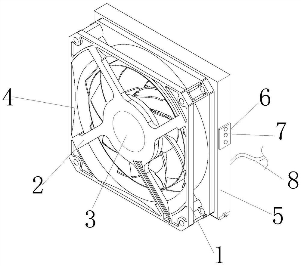
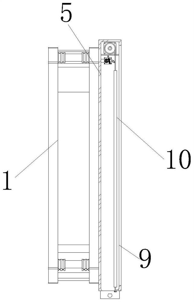
[0029] see figure 1 and figure 2 , the present invention provides a special cleaning device for a resistance load box through improvement, including a fixed frame 1, a rotating groove 4, a fixed frame 5, a discharge groove 9 and a blocking collection mechanism 10, the fixed frame 1 and the connecting frame 2 rear ends Bolt connection, the connecting frame 2 is locked and fixed with the front end of the fan 3 by screws, the middle part of the fixed frame 1 is provided with a rotation groove 4, the blocking collection mechanism 10 is installed and fixed inside the fixed frame 5, the fixed frame 1 is connected with the front end of the fixed frame 5 by bolts, and fixed The right end of the frame 5 is provided with a control panel 6, the front end of the control panel 6 is provided with a button 7, the rear end of the fixed frame 5 is fixed with a power lead 8, and the right end of the fixed frame 5 is provided with a discharge groove 9.

[0030] see image 3 , the present inve...

Embodiment 2

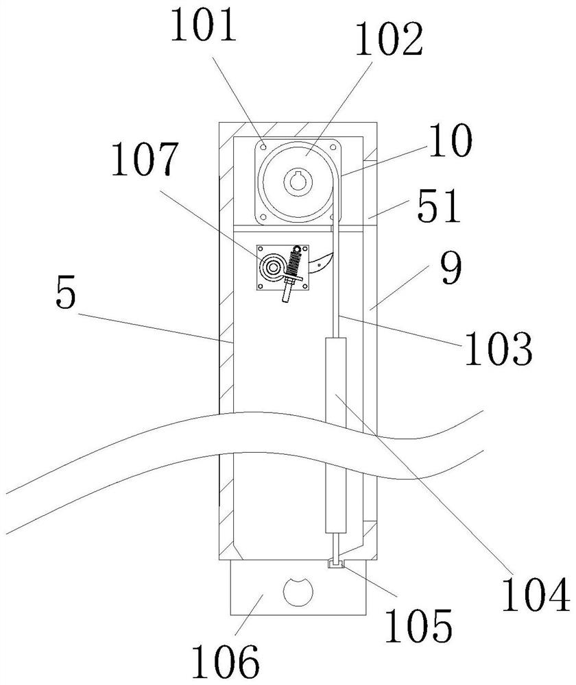
[0034]The present invention provides a dust cleaning device dedicated to the resistance load box through improvement. The scraper 1073 is arc-shaped, and the scraper 1073 is in contact with the left end of the blocking cloth 103, which is beneficial to scrape the dust from the upper end of the blocking cloth 103. , motor 101 and recovery roller 102 centerlines are perpendicular to the same horizontal direction, which is conducive to playing the role of making recovery roller 102 rotate smoothly.

[0035] The present invention provides a dedicated dust removal device for resistance load boxes through improvement, and its working principle is as follows;

[0036] First, before use, place the dust-cleaning device dedicated to the resistance load box horizontally, so that the fixing frame 1 can fix and support the device;

[0037] Second, when in use, connect the external power supply through the power lead 8 to provide power to the device, then press the button 7 on the top of th...


PUM


Abstract

The invention discloses a dust removal device special for a resistive load box. The dust removal device comprises a discharge groove and a blocking collecting mechanism; the blocking collecting mechanism is arranged in a fixing frame, a motor is electrified to work to drive a recovery roller to rotate, and accordingly, the recovery roller releases the winding of blocking cloth; the blocking clothis driven to move towards the lower end through the gravity of a balancing weight, then the blocking cloth blocks the discharge groove, then a draught fan pumps dust, the dust is blown to the upper end of the blocking cloth and falls into a collecting frame to be collected, meanwhile, air flow is exhausted through an air exhaust groove, and the advantage of preventing the dust from flying away isachieved; and a scraping mechanism is arranged at the upper end of the blocking collecting mechanism, a scraping piece makes contact with the left end of the blocking cloth, when the blocking cloth isretracted towards the upper end, the scraping piece can scrape away dust adhering to the upper end of the blocking cloth, and the advantage that dust can be stably scraped away is achieved.

Description

technical field [0001] The invention relates to the related field of resistance load boxes, in particular to a special dust cleaning device for resistance load boxes. Background technique [0002] The resistance load box is mainly used in electric power, telecommunications and other departments and manufacturers' on-line high-power UPS, inverter, switching power supply and diesel generator set performance testing, aging and other occasions, unified segmented power input, energy-consuming working mode , Forced air-cooled heat dissipation, greatly ensuring the reliability of constant power discharge. [0003] When the resistance load box is used, it is often necessary to clean the dust inside the load box with the dust removal device. The current special dust removal device for the resistance load box generally has a simple structure, and the dust is blown out from the inside of the load box by a fan. When the dust is scattered, the existing dust removal device dedicated to t...

Claims


Application Information

Patent Timeline
Patent Type & Authority Applications(China)
IPC IPC(8): B08B5/04B01D46/10B01D46/00B08B15/04
CPCB08B5/04B01D46/10B08B15/04B01D46/681
Inventor 杨立峰程琼
Owner HANGZHOU VOCATIONAL & TECHN COLLEGE
Why Eureka
Try Eureka