Chemical barrel cleaning device for multistage driving type line body operation

A technology for cleaning devices and chemical barrels, applied in the chemical industry, can solve the problems of not necessarily having a drainage outlet, low operation efficiency, inconvenient sewage discharge, etc., and achieve the effect of convenient and effective overall operation.

Inactive Publication Date: 2021-03-09
李洋
View PDF1 Cites 2 Cited by
  • Summary
  • Abstract
  • Description
  • Claims
  • Application Information

AI Technical Summary

Problems solved by technology

[0004] This patent is similar to the structure of many existing chemical barrel cleaning equipment, but there are also great technical defects. The cleaning equipment does not work with chemical barrels, and needs to clean multiple chemical barrels regularly. This type of structure is only a single Station operation, low working efficiency; and the chemical barrel itself is a barrel structure, and there may not be a drain in the barrel. After each cleaning, it is inconvenient to discharge the cleaned sewage

Method used


Image

  • Chemical barrel cleaning device for multistage driving type line body operation
  • Chemical barrel cleaning device for multistage driving type line body operation
  • Chemical barrel cleaning device for multistage driving type line body operation

Examples


Embodiment 1

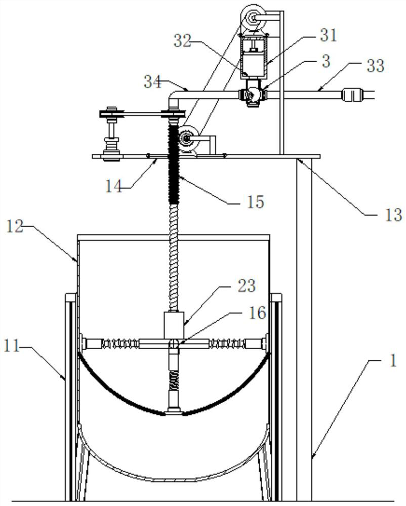
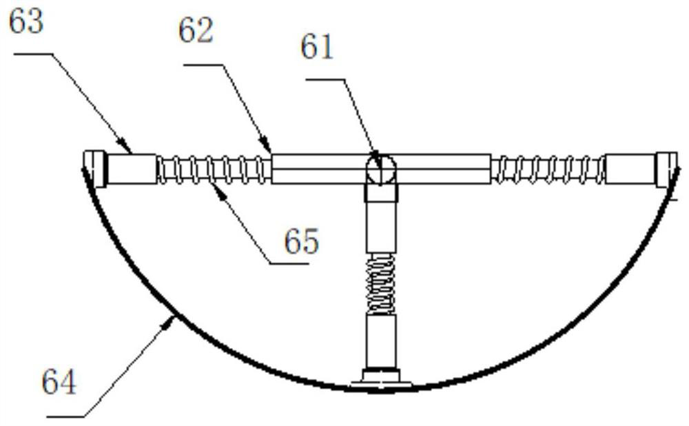
[0031] see figure 1 and figure 2 , a multi-stage drive-type linear operation chemical tank cleaning device, comprising an equipment frame 1, the equipment frame 1 is provided with a support frame 11, a chemical tank 12 is erected on the support frame 11, and the chemical tank 12 The top is provided with a driving frame 13, and the top of the driving frame 13 is provided with a mounting seat 14, and a cleaning rod 15 is installed in the mounting seat 14, and a cleaning frame 16 is provided at the bottom of the cleaning rod 15. The middle position of cleaning frame 16 is provided with trilateral support 61, and the trilateral branch of described trilateral support 61 is provided with branch rod 62, and the outer end of described branch rod 62 is all provided with cleaning head 63, and between described cleaning head 63 An arc-shaped soft cleaning cloth 64 is connected between them, and a spring telescopic rod 65 is arranged between the branch rod 62 and the cleaning head 63 . ...

Embodiment 2

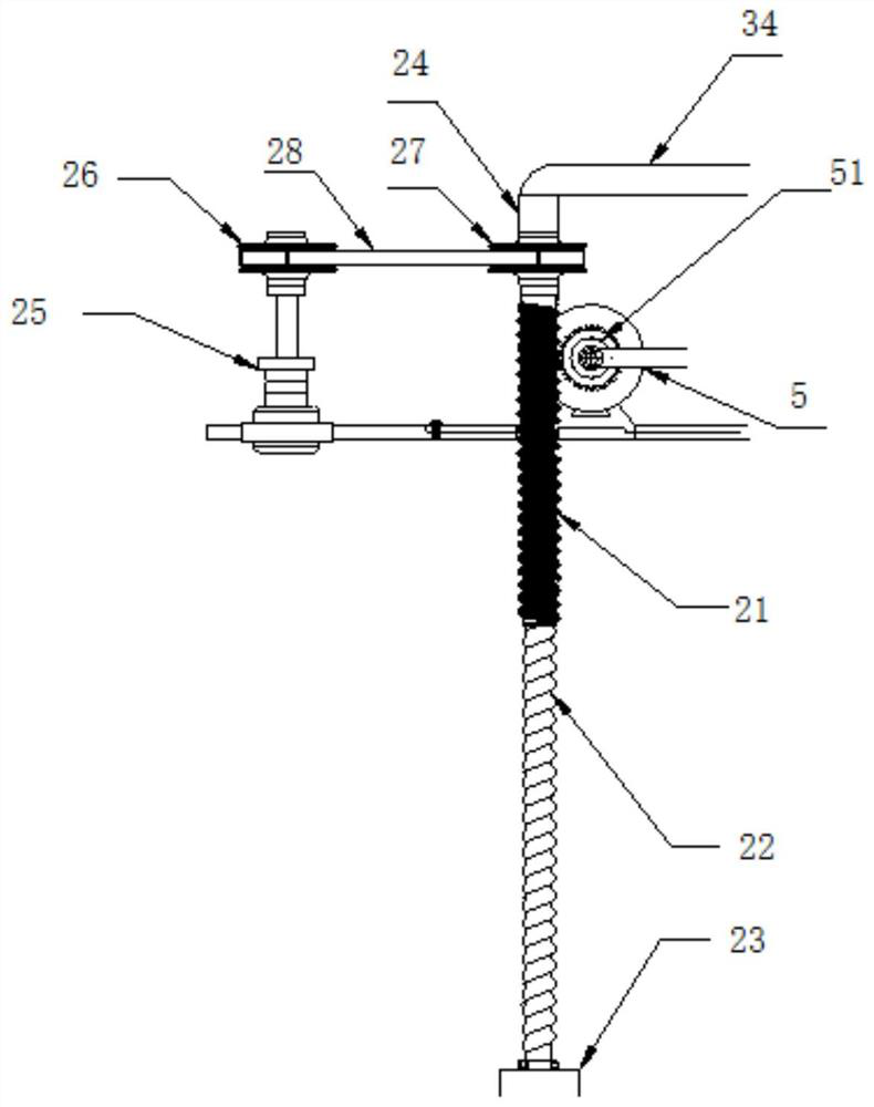
[0039] see figure 1 , image 3 and Figure 5 , in embodiment one, the working procedure of its pumping tube 31 and the working procedure of cleaning bar 15 are independent of each other, but in the present application, pumping tube 31 maintains the consistency of operation, can reach best working requirement; Therefore this implementation Example As a further optimization of the first embodiment, on the basis of it, the support frame 11 is provided with a transmission medium frame 5, and the transmission medium frame 5 is provided with a driven turbine 51, a medium turntable 52 and a secondary driven wheel 53 ; The driven turbine 51 is engaged with the external thread of the external drive rod 21 for transmission, the driven turbine 51 and the medium turntable 52 are coaxially driven, and the medium turntable 52 and the secondary driven wheel 53 The media synchronous rollers 54 are connected by unloadable media synchronous rollers. The media synchronous rollers 54 are driven...


PUM


Abstract

The invention relates to the technical field of chemical engineering, in particular to a chemical barrel cleaning device for multistage driving type line body operation. The chemical barrel cleaning device comprises an equipment frame, wherein a supporting frame is arranged on the equipment frame, a chemical barrel is erected on the supporting frame, a driving frame is arranged at the top of the chemical barrel, a mounting base is arranged at the top of the driving frame, and a cleaning rod part is mounted in the mounting base; a cleaning frame is arranged at the bottom end of the cleaning rodpart, the cleaning rod part comprises an external driving rod part and an internal lifting rod part, the external driving rod part and the internal lifting rod part are each provided with an inner hollow structure, and threads are arranged on the inner wall and the outer wall of the external driving rod part; and an external lifting rod part is arranged in a pipe inner cavity of the external driving rod part in a penetrating manner and connected with the pipe inner cavity through internal threads, and a water discharging cylinder is arranged at the joint between the bottom end of the internallifting rod part and the cleaning frame. According to the chemical barrel cleaning device, the chemical barrel can be comprehensively and effectively cleaned, sewage does not need to be discharged from the chemical barrel, and the modern high-efficiency line body operation process is met.

Description

technical field [0001] The invention relates to the technical field of chemical industry, in particular to a multi-stage driven linear chemical tank cleaning device. Background technique [0002] The chemical mixing tank is generally composed of an upper cylindrical bucket and a lower conical bucket. At present, the cleaning method of the chemical mixing tank is combined with water washing and stirring rod cleaning. The disadvantage is that the inner wall of the mixing tank is non-contact with the stirring rod. If the flushing is not thorough, some raw materials will remain on the inner wall, resulting in insufficient cleaning of the chemical barrels. [0003] Chinese patent (authorized announcement number: CN208866099U) discloses a chemical barrel cleaning device in the chemical industry. The chemical barrel cleaning device is used in the chemical industry. By putting the chemical barrel body inside the fixing device, the fixing device fixes the chemical barrel body , add ...

Claims


Application Information

Patent Timeline
Patent Type & Authority Applications(China)
IPC IPC(8): B08B9/087
CPCB08B9/087
Inventor 李洋
Owner 李洋
Why Eureka
Try Eureka