Workpiece stamping device with clamping function

A stamping device and clamping component technology, applied in the field of stamping devices, can solve problems such as high stamping pressure and workpiece deviation

Inactive Publication Date: 2021-03-09
钟德养
View PDF0 Cites 4 Cited by
  • Summary
  • Abstract
  • Description
  • Claims
  • Application Information

AI Technical Summary

Problems solved by technology

[0002] In the process of workpiece processing, it is often necessary to stamp the workpiece with the help of a stamping device. However, due to the high pressure of the stamping tool on the workpiece, the workpiece is easy to shift during the stamping process. Therefore, it is necessary to provide a clamping function. workpiece stamping device

Method used


Image

  • Workpiece stamping device with clamping function
  • Workpiece stamping device with clamping function
  • Workpiece stamping device with clamping function

Examples


Embodiment 1

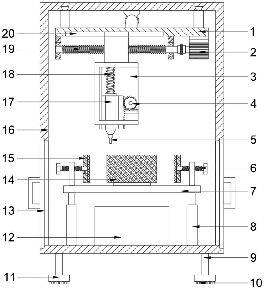
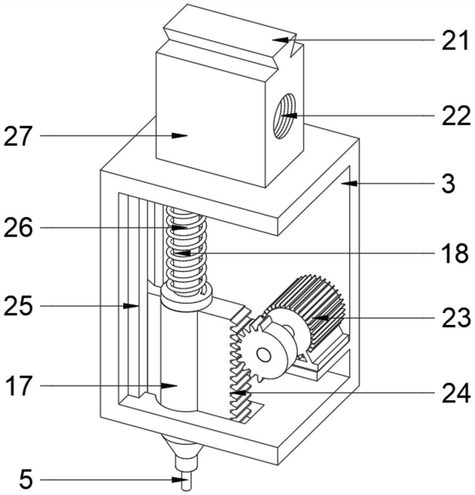
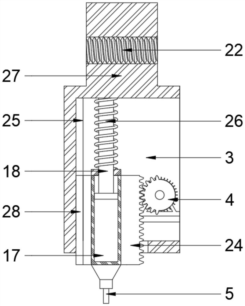
[0024] see Figure 1~4 , in an embodiment of the present invention, a workpiece stamping device with a clamping function includes a box body 16 and a stamping assembly and a clamping assembly arranged inside the box body 16, the stamping assembly includes a stamping mechanism, a first adjustment device and The second adjustment device, the stamping mechanism is threaded on the second adjustment device, the upper end of the first adjustment device is slidably installed on the top of the box body 16 and its lower end is fixedly connected with the second adjustment device; the first adjustment device Cooperate with the second adjustment device to drive the stamping mechanism to slide back and forth, left and right, and stamp at different positions of the workpiece, which is practical; the clamping assembly includes a workbench 7, a lifting rod 8 and a clamping device, and the workbench 7 is lifted by lifting Rod 8 is fixedly installed below the stamping mechanism and multiple gro...

Embodiment 2

[0031] see figure 1 , in an embodiment of the present invention, a workpiece stamping device with a clamping function, in order to prevent the debris generated by stamping from being scattered everywhere, on the basis of Embodiment 1, a waste box is also provided at the inner bottom of the box 16 12. The waste box 12 is placed under the workbench 7 and its position corresponds to the box door 13. The waste box 12 is used to collect the debris produced by the stamping tool 5 stamping the workpiece. Through the box door 13, the The waste bin 12 with debris is taken out from the inside of the casing 16 .

[0032] The working principle of the present invention is:

[0033] When working, rotate the support plate 11 to adjust the matching length of the support device and use the buffer pad 10 to support the device on the ground to keep the device stable; open the box door 13, place the workpiece on the workbench 7, and turn the four sets of clamping bolts 6 Adjust the distance bet...


PUM


Abstract

The invention discloses a workpiece stamping device with a clamping function. The workpiece stamping device with the clamping function comprises a box body, a stamping assembly and a clamping assembly, the stamping assembly and the clamping assembly are arranged inside the box body, the stamping assembly comprises a stamping mechanism, a first adjusting device and a second adjusting device, the clamping assembly comprises a workbench, lifting rods and a clamping device, the clamping device comprises clamping bolts and clamping plates, the four clamping bolts are in threaded connection with mounting plates correspondingly, and the four clamping plates are rotationally connected with the four clamping bolts correspondingly. According to the workpiece stamping device with the clamping function, the clamping bolts and the clamping plates are matched with the workbench and the lifting rods to clamp workpieces of different sizes, and protection pads are matched to prevent the clamping platesfrom excessively clamping the workpieces to damage the edges of the workpieces; and a stamping sliding sleeve and a stamping sliding rod are adopted, an incomplete gear is matched with a rack, a stamping motor is used for driving to drive a stamping tool to ascend, the elastic force effect of a stamping spring is used for driving the stamping tool to quickly descend, and stamping of the workpieces is achieved.

Description

technical field [0001] The invention relates to a stamping device, in particular to a workpiece stamping device with a clamping function. Background technique [0002] In the process of workpiece processing, it is often necessary to stamp the workpiece with the help of a stamping device. However, due to the high pressure of the stamping tool on the workpiece, the workpiece is easy to shift during the stamping process. Therefore, it is necessary to provide a clamping function. workpiece stamping device. Contents of the invention [0003] The object of the present invention is to provide a workpiece stamping device with a clamping function to solve the problems raised in the above-mentioned background technology. [0004] To achieve the above object, the present invention provides the following technical solutions: [0005] A workpiece stamping device with a clamping function, comprising a box body and a stamping assembly and a clamping assembly arranged inside the box bod...

Claims


Application Information

Patent Timeline
Patent Type & Authority Applications(China)
IPC IPC(8): B21D22/02B21D43/00B21D43/20
CPCB21D22/02B21D43/003B21D43/20
Inventor 钟德养
Owner 钟德养
Why Eureka
Try Eureka