Welding power supplies and user interfaces for welding power supplies

An interface and electric power technology, applied in welding equipment, arc welding equipment, manufacturing tools, etc., can solve problems such as inability to produce weld seams, insufficient arc action to produce weld seams, and difficulty in adjusting welding parameters

Pending Publication Date: 2021-03-09
ILLINOIS TOOL WORKS INC
0 Cites 0 Cited by

AI-Extracted Technical Summary

Problems solved by technology

If the operator does not adjust the voltage and wire feed speed settings properly, the arc action may not be sufficient to produce a good weld, or any weld at all
Additionally, in conventional setups, wir...

Abstract

Example disclosed power supplies, user interfaces, and methods are provided for simple and intuitive setting of configurable settings and/or default settings of a welding power source and/or a wire feeder. The welding parameters may correspond to default settings and/or factory settings that represent empirical citation values for a particular welding process (e.g., based on material type, electrode diameter, welding process and/or tool, etc.). The welding parameters may additionally or alternatively be configured for particular purposes. Once the configurable setting is selected, the configurable setting controls the system output. Further, once a set of configurable welding parameters has been established, the operator may return to the default settings by resetting the welding parameters.

Application Domain

Arc welding apparatus

Technology Topic

Material typeProcess engineering +6

Image

  • Welding power supplies and user interfaces for welding power supplies
  • Welding power supplies and user interfaces for welding power supplies
  • Welding power supplies and user interfaces for welding power supplies

Examples

  • Experimental program(1)

Example Embodiment

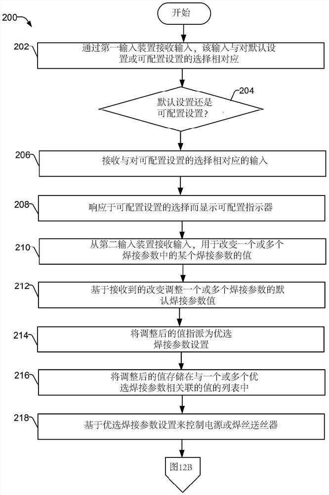
[0017] The disclosed example power supply, user interface, and method allow for simple and intuitive settings for the configurable settings and / or default settings of the welding power source and / or the filament.
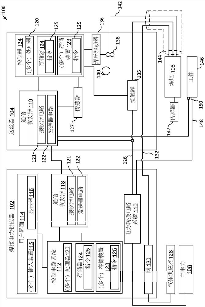
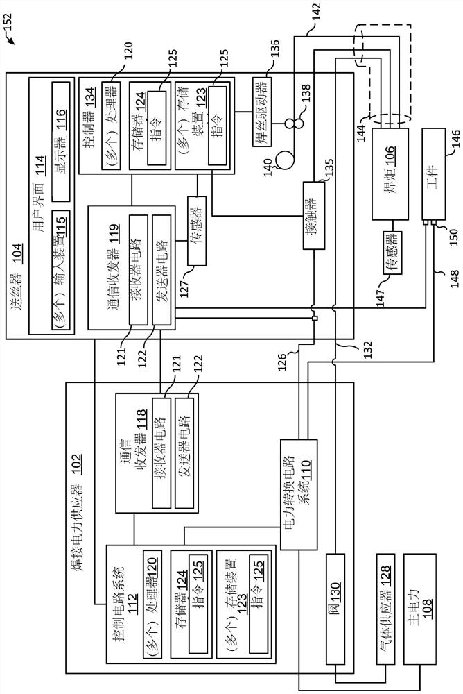
[0018] In some examples, the welding system includes a power source for one or more soldering parameters (e.g., voltage, current, electricity, wire speed, gas flow rate, pulse rate, workpiece thickness, workpiece material type, electrode type, welding process) , Travel speed, arc length or joint type, etc.) deliver power to the torch. As disclosed herein, the welding parameters may correspond to the default settings and / or factory settings, which represent empirical reference values ​​for specific welding processes (for example, material type, electrode diameter, welding process and / Or tool, etc.). Welding parameters can be configured for specific purposes. In other words, an interface (such as an auto setting button) can be provided to allow the operator to adjust one or more solder parameters. The second input device (such as selector switch, knob, touch screen input) receives input from the operator to the desired change of the value of one or more solder parameters. Once the configurable setting is selected, the configurable settings control the system output without additional input. After establishing a set of controlled welding parameters, the controller controls the power supply transport power or the control welding wire feeder to advance the electrical wire based on the controlled welding parameter setting.
[0019] In addition, once a set of configurable welding parameters are established, the operator can return to the default setting by resetting the welding parameters. For example, the operator can provide an input corresponding to the selection that returns to the default welding parameter setting using the auto setting button. The controller can then access the default welding parameter setting from a value associated with one or more default welding parameters (eg, corresponding to best practices, values ​​obtained by experience, etc.). After successful resets, based on the default welding parameter setting, the power supply is transported or solder wire feeder to advance the electrical wire.
[0020] The state of the welding parameter (for example, whether the setting corresponds to the default setting or the configuration configured) and the parameter value can be displayed on the display device presenting to the operator. For example, the display can include an information bar to display graphics or text corresponding to the instruction or response to the operator to help adjust the welding parameter setting.
[0021] In the disclosed example, a welding system includes: a power source configured to deliver power to a torch based on one or more soldering parameters; wire wire cleaner, the wire wire cleaner is configured based on the one Or multiple weld parameters proceed to the welding torch; and the interface. The interface includes: a first input device configured to receive an input corresponding to the selection of the default setting or configurable setting of the one or more solder parameters; display device, the display device is configured to The default indicator is displayed in response to the selected default setting, or the configurable indicator is displayed in response to selecting a configurable setting; and the second input device, the second input device is configured to receive the one or more welding parameters. Value changes related to input. The control circuitry is included and configured to receive an input corresponding to the selection of the configurable set; from the second input device receives some of the welding parameters in the one or more soldering parameters. The value of the value changes corresponding to the input; the default welding parameter value of the one or more soldering parameters is adjusted from the default welding parameter value of the one or more solder parameters, and the adjusted value is assigned to the preferred welding parameter setting, and will be adjusted The value is stored in a list of values ​​associated with one or more preferred welding parameters; based on the preferred welding parameter setting, the power supply is transmitted or controlled to advance the wire wire; from the first input device Receive the input corresponding to the selection of the default welding parameter; access the default welding parameter setting from a list associated with one or more default welding parameters; and control the power supply to transmit power based on the default welding parameter setting or Controlling the wire wire feeder makes the electrode wire.
[0022] In some examples, the control circuitry applies one or more adjustment boundaries such that the adjustment of the default welding parameter value is limited by the one or more adjustment boundaries. In the example, the one or more adjustment boundaries are five percent of the default welding parameter value. In some examples, the one or more adjustment boundaries correspond to a predetermined value.
[0023] In an example, the interface includes a graphical range indicator to indicate the default welding parameter range or the welding parameter threshold range such that the upper limit value is indicated on the first side of the default welding parameter range, and the default welding parameter range The opposite side opposite to the first side indicates the lower limit.
[0024] In some examples, the interface includes a graphical crossline that indicates the default welding parameter. In an example, the interface includes an indication of a graphic strip that selects a configurable welding parameter. In some examples, the graphic belt corresponds to the value of the welding parameter relative to the default welding parameter in the position of the drawing parameter. In the example, the input type is clicked, double-click or holds one of the input devices to last for a predetermined amount of time, which corresponds to different functions of the corresponding device.
[0025] In some examples, the control circuitry is further configured to control the power supply transmission power in accordance with one or more welding processes, each of which each welding process in the one or more soldering processes corresponds to one or more configurable settings. In an example, the one or more soldering parameters include voltage, current, electricity, wire speed, gas flow rate, pulse rate, workpiece thickness, workpiece material type, electrode type, welding process, travel speed, arc length, or connector type One or more people.
[0026] In the disclosed example, a welding system includes: a power source configured to deliver power to a torch based on one or more solder parameters; wire wire cleaner, the wire wire wire is configured to be based on this One or more soldering parameters advance the wire electrodes to the torch, wherein the one or more soldering parameters include a voltage or a wire feed speed; an interface. The interface includes: a first input device configured to receive an input corresponding to the selection of the default setting or configurable setting of the one or more solder parameters; display device, the display device is configured to The default indicator is displayed in response to the selected default settings, or the configurable indicator is displayed in response to selecting configurable settings. The voltage selection knob receives an input associated with the voltage supplied to the torch, and the filament speed selection knob receives input from the wire wire feeder. The control circuitry receives the input corresponding to the selection of the configurable set; the control circuit is received; the input corresponding to the value of one or more of the filament speed; based on the received Changing the value of the voltage or the transmission speed; the value of the adjustment of the voltage or the filament speed is assigned to the preferred welding parameter setting, and store the adjusted value in association with one or more preferred welding parameters. In the list of values; and based on this preferred welding parameter setting, the power supply is transmitted or controlled to move the electrical wire.
[0027] In some examples, the control circuitry receives an input corresponding to the selection set to the default welding parameter; accesses the default welding parameter setting from a list associated with one or more default welding parameters. ; And based on the default welding parameter setting to control the power supply to transport electricity or control the wire wire feeder to advance the electrical wire.
[0028]In some examples, the information column is used to display graphical or text to the operator, the graphic or text provides instructions or responses corresponding to the user input. In an example, the interface includes a welding process type input device configured to receive an input related to the type of welding process, wherein at least partially, based on the type of welding process, the value and default welding of the power output is calculated based on the type of welding process. The range of parameter values.
[0029] In some examples, the welding process type input device includes an optional option for one or more soldering processes in a metal inert gas (MIG) or tungsten inert gas (TIG) welding process as a welding process type. In an example, the interface includes a workpiece input device configured to receive an input related to the material thickness of the workpiece, wherein the control circuitry is further configured to determine the default welding parameter value based on the thickness of the material.
[0030] In some examples, the interface includes a first graphic range indicator with an indication of the current value of the voltage and a second graphics range indicator with an indication of the current value of the wire feed speed. In an example, the control circuit system is further configured to update the current value of the parameter of the voltage in response to the input received via the voltage input device, and in response to input received via the transmission speed input device Update the indication of the current value of the wireless speed.
[0031] In some examples, the control circuitry is further configured to apply one or more adjustment boundaries such that the adjustment of the default welding parameter value is limited by the one or more adjustment boundaries.
[0032] As used herein, "power conversion circuitry" and / or "power conversion circuit" refers to converting power from one or more first forms (e.g., power output from generators) to have voltage, current, One or more second forms of circuitry and / or electrical components of any combination of frequency and / or response characteristics. The power conversion circuitry can include a secure circuit system, an output selection circuitry, a measurement, and / or control circuitry and / or any other circuit for providing appropriate features.
[0033] As used herein, the terms "first" and "second" can be used to list different components or elements of the same type, and do not necessarily imply any particular order.
[0034] The term "welding system" as used herein includes any device capable of supplying electric power suitable for welding, plasma cutting, induction heating, CAC-A, and / or hot wire welding / preheating (including laser welding and laser classes). The device includes an inverter, a converter, a chopper, a resonant power supply, a quasi-resonant power supply, or the like, and a control circuitry and other auxiliary circuit systems associated therewith.
[0035] As used herein, the term "welding power" refers to electricity suitable for welding, plasma cutting, induction heating, CAC-A, and / or hot wire welding / preheating (including laser welding, laser cladding). As used herein, the term "welding type power supply" and / or "power supply" refers to welding, plasma cut, induction heating, CAC-A and / or hot wire welding when power is applied to it. Preheat (including laser welding and laser cladding) Any means of power, including, but not limited to, inverters, converters, resonant power supplies, quasi-resonant power supplies, etc., and control circuitry and other control circuitry related to it Auxiliary circuit system.
[0036] As used herein, "circuit" or "circuitry" includes any analog and / or digital components, power, and / or control elements (such as microprocessors, digital signal processors (DSPs), software, etc.), discrete components and / Or integrated components, or multiple parts and / or combinations thereof.
[0037] The terms "control circuit", "control circuitry", / or "controller" as used herein may include digital and / or analog circuitry, discrete, and / or integrated circuit systems, microprocessors, digital signal processors (DSP) ) And / or other logic circuitry, and / or associated software, hardware, and / or firmware. Control circuitry or control circuitry can be located on one or more boards that form a part or all of the controller, and is used to control a welding process, such as a power supply or a wire or other means, and / or any other type of Welding related system.
[0038] As used herein, the term "memory" includes volatile and nonvolatile memory devices and / or other storage devices.
[0039] As used herein, the term "torch", "torch", welding tool, or "welding tool" refers to a device configured to be manipulated to perform welding-related tasks, and may include hand-held welding torch, robot welding torch, Welding torches or other devices for generating welding arcs.
[0040] As used herein, the term "welding mode", "welding process", "welding process" or "welding operation" refers to the type used, such as current control (CC), voltage control (CV). , Pulse, gas protection melting electrode arc welding (Gmaw), flux, tungsten gas protection (GTAW), protected metal arc welding (SMAW), spray, short circuit, and / or any other type Welding process.
[0041] As used herein, the term "welding procedure" includes at least one set of welding parameters for controlling welding. The welding procedure can further include other software, algorithms, procedures, or other logic for controlling one or more welding devices to perform welding.
[0042] Turning now to the drawings, Figure 1A It is a block diagram of an example welding system 100 having a welding type power supply 102, a wire feeder 104, and a torch 106. Welding system 100 is powered to welding, control welding applications and supplies consumables to the welding to provide simple and intuitive settings for the configurable settings and / or default settings of the power supply 102 and / or the wire feeder 104. In other words, an interface (such as an auto setting button) can be provided to allow the operator to adjust one or more solder parameters. The second input device (e.g., selector switch, knob, touch screen input) receives inputs related to the desired change of the value of one or more solder parameters to establish configurable settings for control without additional input. System output. In addition, once a set of configurable welding parameters have been established, the operator can return to the default setting by resetting the welding parameters.
[0043] In some examples, the power supply 102 supplies input power to the torch 106. Based on the desired welding application, the torch 106 can be configured for the protected metal arc welding (SMAW, or electrode welding), tungsten material, gas protection, gas-protecting, gas, gas protection, gas, gas protection Welding torch of core arc welding (FCAW). In the illustrated example, the power supply 102 is configured to supply power to the filament 104, and the filament 104 can be configured to transfer the input power to the torch 106. In addition to supplying input electricity, the wire feeder 104 can also supply a filler metal to the torch 106 for various welding applications (eg, Gmaw welding, flux core arc welding (FCAW)). in spite of Figure 1A The example system 100 includes a wire feeder 104 (e.g., for GmAW or FCAW welding), but the filament 104 can be replaced by any other type of remote accessory device, such as providing electrode welding and / or TIG welding solder welding and / Or TIG welding remote control interface.
[0044] The power supply 102 receives main power 108 (e.g., from the AC grid, engine / generator set, battery, or other energy generation or storage device, or a combination thereof), adjusting the main power, and to one or more of the requirements of system 100 The welding device provides output power. The main power 108 can be supplied from a different location (e.g., main power can be derived from the grid). The power supply 102 includes a power conversion circuit system 110, which may include a transformer, a rectifier, a switch, or the like, which can convert the AC input power to the need (eg, a particular welding process and solution). AC and / or DC output power. The power conversion circuit system 110 converts the input power (e.g., main power 108) into a welding power based on the welding voltage set point, and outputs the welding type electric power via the welding circuit.
[0045] In some examples, the power conversion circuit system 110 is configured to convert the main power 108 into welding type power output and auxiliary power output. However, in other examples, the power conversion circuit system 110 is adapted to convert only the main electric power to a welding power output, and provide a separate auxiliary converter 111 to convert the main power into a auxiliary power. In some other examples, the power supply 102 receives the converted auxiliary power output directly from the wall outlet. The power supply 102 can produce and supply welding power and auxiliary electricity using any suitable power conversion system or mechanism.
[0046] The power supply 102 includes a control circuitry 112 for controlling the operation of the power supply 102. Power supply 102 also includes a user interface 114. Control circuitry 112 receives input from user interface 114, by which user can select process and / or input desired parameters (eg, voltage, current, specific pulses or non-pulsed welding schemes, etc.). User interface 114 can use one or more input device 115 to receive input, such as via a keypad, a keyboard, an entity button, a touch screen (for example, a software button), a voice activation system, a wireless device, and the like. Further, the control circuitry 112 controls the operation parameters based on the user's input and based on other current operation parameters. Specifically, user interface 114 can include display 116, which is used to present, or indicate information to the operator. Control circuitry 112 can also include an interface circuitry for transferring data to other devices in system 100, such as a filament 104. For example, in some cases, the power supply 102 wirelessly communicates with other welding devices within the welding system 100. Further, in some cases, the power supply 102 communicates with other welding devices using a wired connection, such as by using the network interface controller (NIC) via a network (e.g., Ethernet, 10Baset, 10BASE100, etc.). in Figure 1A In the example, the control circuitry 112 communicates with the wire feeder 104 via the communication transceiver 118, as described below.
[0047] Control circuitry 112 includes at least one controller or processor 120 that controls the operation of the power supply 102. Control circuitry 112 receives and process multiple inputs associated with the performance and requirements of system 100. Processor 120 can include one or more microprocessors, such as one or more "universal" microprocessors, one or more dedicated microprocessors, and / or ASICs, and / or any other type of processing device. For example, processor 120 can include one or more digital signal processors (DSPs).
[0048] Example control circuitry 112 includes one or more memory device 123 and one or more memory device 124. (Multiple) memory device 123 (eg, non-volatile storage devices) may include ROM, flash memory, hard drive, and / or any other suitable optical storage medium, magnetic storage medium, and / or solid state storage medium And / or a combination thereof. The memory device 123 stores data (e.g., data corresponding to welding applications), instructions (e.g., software or firmware for performing welding processes) and / or any other suitable data. An example of a storage data for welding applications includes a posture (e.g., orientation) that contacts the distance, voltage, current, welding device arrangement between the end and the workpiece.
[0049]Memory device 124 can include a volatile memory (such as a random access memory (RAM)) and / or non-volatile memory (eg, read only memory (ROM)). Memory device 124 and / or (multiple) memory device 123 can store various information and can be used for various purposes. For example, memory device 124 and / or (plurality) memory device 123 can store processors (e.g., firmware or software) performed by processor 120. Further, one or more control scheme for various welding processes, together with the associated settings and parameters, can provide a specific output during operation (for example, start sending wire, allowing gas flow, capturing welding current) Data, detection short-circuit parameters, determine the splash amount) of the memory device 123 and / or memory device 124 together. One or more lists or lookup tables can be provided, and / or provide network connections to various databases that can be used to make decisions to access preferred welding parameters, store updated welding parameter settings, and the like.
[0050] In some examples, welding power flows from the power conversion circuit system 110 to the wire feeder 104 and the torch 106 by welding cable 126. Example welding cable 126 can be attached to the welding studs at each of the power supply 102 and the wire feeder 104, and can be easily removed from the welded stud (for example, in the case of wear or damage. Line 126). Moreover, in some examples, welding data is provided by welding cable 126 such that welding power and welding data are provided and transmitted together by welding cable 126. Communication transceiver 118 is communicatively coupled to welding cable 126 to transmit (eg, transmit / receive) data by welding cable 126. Communication transceiver 118 can use serial communication (eg, full duplex RS-232 or RS-422, or half-duplex RS-485), network communication (eg, Ethernet, PROFIBUS, IEEE 802.1x wireless communication, etc.), Parallel communications and / or any other type of communication technology is implemented. In some examples, communication transceiver 118 can be implemented by welding cable 126.
[0051] Example communication transceiver 118 includes a receiver circuit 121 and a transmitter circuit 122. Typically, the receiver circuit 121 receives data transmitted by the filament 104 via the welding cable 126, and the transmitter circuit 122 transmits data to the filament 104 via the weld cable 126. The communication transceiver 118 can remotely configure the power supply 102, and / or command and / or control the wire feed speed output by the wire 104 and / or the welding power output by the electric power supply 102 ( For example, voltage, current).
[0052] Example filament 104 also includes a communication transceiver 119 that can be similar or identical or identical to communication transceiver 118 in structure and / or functionality. Although in Figure 1A The communication is shown in a separate communication cable, but other communication media, such as wireless media, power line communications, and / or any other communication medium can also be used.
[0053] In some examples, gas supply 128 provides protective gas such as argon, helium, carbon dioxide, and the like according to welding applications. Protect the gas flow valve 130, the valve controls the flow of the gas, and if necessary, the valve can be selected to allow adjustment or adjustment of the amount of gas supplied to the welding application. Valve 130 can be operated by control circuit system 112, close or otherwise operated to allow, prohibit or control gas (eg, protective gas) flow through valve 130. The protective gas leaves the valve 130 and passes through the cable 132 (in some embodiments, it can be combined with the welding power output) to the wire feeder 104, thereby providing a protective gas for the welding application. In some examples, the welding system 100 does not include a gas supply 128, a valve 130, and / or a cable 132.
[0054] In some examples, the wire feeder 104 is powered by various components in the wire feeder 104, such as supplying electric wire controller 134. As described above, the welding cable 126 can be configured to provide or supply welding power. The power supply 102 can also communicate with the communication transceiver 119 disposed with the wire communication transceiver 118 disposed within the power supply 102 in the power supply 102. In some examples, the communication transceiver 119 is substantially similar to the communication transceiver 118 of the power supply 102. The filament controller 134 controls the operation of the wire feeder 104. In some examples, the filament 104 uses a wire controller 134 to detect whether the filament 104 communicates with the power supply 102, and if the filament 104 communicates with the power supply 102, the power supply 102 is detected. Current welding process.
[0055] Contactor 135 (e.g., high ampere relay) is controlled by a filament controller 134 and is configured to allow or disable welding power to continue to flow to the welding cable 126 for welding applications. In some examples, the contactor 135 is a mechanismer. However, contactor 135 can be any other suitable device, such as a solid state device. The wire driver 104 includes a wire driver 136 that receives a control signal from the filament controller 134 to drive the roller 138, which is rotated to pull the wire wire wire shaft 140. The wire is supplied to the welding application through the welding torch cable 142. Similarly, the filament 104 can provide a protective gas from the gas supply 128 through the cable 142. Electrode wire, protective gas, and power from the solder cable 126 are combined together in a single torch cable 144 and / or separately to the welding torch 106. In some examples, the contactor 135 is omitted, and the power is started and stopped by the power supply 102. In some examples, the filament 102 includes or connected to one or more sensors 127 to monitor one or more soldering parameters (eg, electric power, voltage, current, wire speed, etc.), such as notification during the welding process. Controller 134. In some examples, the welding power supply 102 includes one or more sensors.
[0056] The torch 106 delivers welding wire, welding electricity, and / or protective gas for welding applications. The torch 106 is used to establish a welding arc between the torch 106 and the workpiece 146. Working cable 148 couples the workpiece 146 to the power supply 102 (e.g., coupled to the power conversion circuit system 110) to provide a return path (e.g., as part of the welding circuit). Example Work Cable 148 can be attached to the power supply 102 and / or removed from the power supply 102 to facilitate replacement of the work cable 148. Work cable 148 can be terminated with a jig 150 (or another power connection device), which coupled to the power supply 102 to the workpiece 146. In some examples, the torch 106 includes or connected to one or more sensor 147 to monitor one or more soldering parameters (e.g., electric power, voltage, current, wire speed, etc.) to notify the control during the welding process. 34 and / or 112.
[0057] Figure 1B It is a schematic diagram of another example welding system 152 in which the wire feeder 104 includes a user interface 114 in addition to the user interface on the welding power supply 102. in Figure 1B In the example, the control circuit system 134 of the filament 104 performs a reference Figure 1A The determination of the welding procedure and welding parameters described in the control circuitry 112.
[0058] Figure 1C It is a schematic diagram of another example welding system 154 including a separate user interface 156. The user interface 156 is a separate device and can be connected to the welding power supply 102 and / or a wire feeder 104 to provide command and / or control information. Example user interface 156 includes an input device 115 and a display 116, and includes a control circuitry 158. Example control circuitry 158 includes a (plurality) processor 120 and memory 124 of the memory instruction 125. The example user interface 156 further includes a communication transceiver 119 for enabling communication between the user interface 156 and the welding power supply 102 and / or the wire.
[0059] in spite of Figures 1A to 1C The user interface (114, 156) that is bonded to a particular system, but the presentation is exemplary, so one or more interfaces disclosed herein and the additional user interface can be combined in one or more example welding disclosed herein. In the system. Further, although the power supply 102 and the wire feeder 104 are shown as a stand-alone unit, in some examples, the power supply and the wire can be accommodated in a single housing or in other ways to be integrated. Additionally or alternatively, in some examples, a single controller, control circuitry, and / or interface can control both the power supply and the wire feeder.
[0060] figure 2 An example user interface 114 for which the adjustable automatic setting process disclosed herein is shown. In some examples, (multiple) welding systems 100, 152, 154 can perform a synergistic mode (once default or custom settings have been established, where control circuitry 112, controller 134, and / or controller 158 are in response to via via via via The selector 52 selects the wire feed speed and the predetermined relationship between the wire feed speed and the voltage to determine the voltage value. In some examples, a predetermined relationship is selected based on a welding procedure or one or more welding parameters including a workpiece type, a thickness of the workpiece thickness. Control circuitry / controller can enable or disable synergism based on the selected welding procedure (e.g., based on a collaborative welding process or non-synergistic welding process).
[0061] When the control circuitry / controller performs a collaborative mode, the control circuitry / controller can determine the thickness of the workpiece or material recommended for the currently selected filament speed and / or welding procedure. For example, for a particular welding procedure and the wire feed speed, the filament speed range can be suitably stored as a list of values ​​associated with one or more soldering parameters (eg, voltage, current, workpiece characteristics) in (multiple). The memory device 123 and / or memory 124 are included.
[0062] figure 2 The example user interface 114 is configured to synergistically adjust the voltage and the wire speed operation based on the selected filament speed, so that the control circuit system / controller determines the relationship between the wire and the voltage and the voltage, and / Or welding process parameters, workpiece properties, wire type parameters, wire size parameters, or corresponding voltage associated with one or more parameters in gas type parameters, all of which can be stored as a list or lookup table (for example, In (multiple) memory device 123, the memory 124 is medium. The control circuitry / circuit is set to the voltage value determined based on this relationship.
[0063] Such as Figures 2 to 11 As shown, the user interface 114 includes a welding process selector 40, an electrode diameter adjuster 42, a material thickness adjuster 44, and automatically sets the selector 46, a color display screen 48 (e.g., merge with the display 116, which is supplemented as the display 116, or Alternate display 116) and welding parameters (e.g., voltage, filament speed, and / or amperage) adjust the turntables 50 and 52. Component about user interface 114 and / or 156 Figures 2 to 11 , but Figures 2 to 11 The same and / or different components, features, features, attributes, and the like can be included.
[0064] Such as figure 2 As shown, the welding process selector 40 can allow the operator or other user to select from a plurality of solder processes. For example, the welding process selector 40 allows the operator from a welding process, one or more metal inert gas (MIG) welding processes, one or more tungsten gas (MIG) welding processes, one or more tungsten gas (MIG) welding processes, one or more tungsten gas (MIG) welding processes Select in the welding process. In addition to the general welding process, in some examples, the welding process selector 40 allows the operator to select the material of the solder electrode. For example, in order to implement the MIG welding process, the operator can select, for example, stainless steel, another type of steel, or aluminum electrode to implement the MIG process. In some examples, the welding process selector 40 allows the operator to select the desired welding process (e.g., the welding rod welding process, MIG welding process, TIG welding process, etc.), the type of electrode material (eg, steel, aluminum, etc.) and gas type ( For example, C25, C100, argon, etc.), and then select the automatic setting function of (multiple) welding systems 100, 152, 154, to automatically synchronize the appropriate voltage and wire speed and / or amperage solder parameters.
[0065] In figure 2 The user interface 114 includes an electrode diameter adjuster 42 (e.g., electrode filaments, electrode rods, or tungsten electrodes, depending on the type of soldering process type). The electrode diameter is an optional welding parameter for performing welding because the number of welding arcs depends on the diameter of the electrode wire. In some examples, the electrode diameter adjuster 42 has some features, such as "+" buttons for increasing the diameter setting of the electrode diameter and "-" button for reducing the diameter setting of the electrode. Similarly, the user interface 114 may also include a material thickness adjuster 44, for example, a material thickness adjuster comprising a "+" button for increasing material thickness setting (eg, related to workpiece 146 to which it is to be welded). Used to reduce the "-" button set of material thickness. The electrode diameter setting and material thickness setting jointly affects the voltage and amperage (e.g., current) for performing a given welding process.
[0066] In some examples, the operator or other user can select the auto setup function via the automatic setting selector 46. When auto-set feature (for example, by operator activation), the operator can input the corresponding electrode diameter setting and material thickness of the power supply 102 to set the desired welding parameters (such as voltage, wire speed, and / or ampere) Number parameters) Automatic adjustment (eg, increasing or decreasing) is appropriate settings.
[0067] in figure 2 In the example, the automatic setting selector 46 is a pass / power-off switch or pass / break button that can be activated or deactivated, allowing the operator to enable or disable the automatic setting function of the welding system 10. In an example, user interface 114 includes one or more lamp indicators 54 (e.g., in some examples) to indicate that the auto setting function is enabled or disabled. For example, during the execution of the MIG welding process, the operator can select the automatic setting function via the automatic setting selector 46, and one or more lamp indicator 54 can display other indications such as blue or enable automatic settings to the operator. In some examples, the welding process selector 40 can be associated with a plurality of lamp indicators 55, each lamp indicator 55, in space, with a label corresponding to the corresponding welding process (eg, "flux core", "MIG stainless steel "Wait) Align, enabling the controlled welding process for the manipulation of the welding process selector 40, and corresponding to the lamp pointer 55 of the selected welding process can display such as blue or selected specific welding processes. Indicates, and other lamp indicators 55 corresponding to other welding processes do not illuminate.
[0068] Regarding the electrode diameter adjuster 42, the material thickness adjuster 44, and the automatic setting selector 46, the user interface 114 includes a color display 48. The color display 48 can be any display device that can display a visual graphic object and / or alphanumeric text related to the real-time operational state of the welding parameter, (plurality) welding system 100, 152, 154. The information bar 64 can provide instructions or alerts associated with the selected welding parameters, welding process, and / or such parameters or processes. in figure 2 In the example, the color display 48 can be capable of displaying the selected electrode diameter (eg, .030 "), the material thickness (e.g., 1/8"), the power supply welding voltage (e.g., 18.0 volts) and a wire feed speed (for example, 310 inches per minute) ).
[0069] In some examples, the welding process selector 40, the electrode diameter adjuster 42, the material thickness adjuster 44, the automatic setting selector 46, the welding parameter adjustment turntables 50 and 52, or any combination can be displayed as in color display screen 48 The graphics input device. For example, color display 48 can be a touch screen that is configured to receive input from the user via the display of these graphics input devices displayed on color display 48. For example, in some examples, instead of the actual physical input device (or supplemental) arranged on the user interface 114, other types of user input elements such as graphic buttons, slors, knobs, etc. displayed via color display screen 48 can be used. To receive input from the user.
[0070] In the disclosed example, when the automatic setting selector 46 is enabled, the color display screen 48 can be based on the input of the electrode diameter and / or material thickness parameters (for example, these inputs may be based on the electrode diameter adjuster 42 and / or). The manipulation of the material thickness adjuster 44 is provided) to display the available value range of the welding voltage and the filament speed and / or the number of amperage. As used herein, the acceptable welding parameter value range can be such a value range: within this value range, the power supply 102 holds voltage and filament in response to the value of the input or estimated electrode diameter and material thickness parameters. The number of speeds and / or ampeals makes welding effectively. For example, if figure 2 As shown, the weld operator can input the thickness of the material of the electrode diameter and 1/8 "by the user interface 114. In response to inputting, power supply 102 can automatically set 18.0 volts and 310 inches per minute to appropriate welding parameters to perform welding for these specific electrode diameter and material thickness properties. The welding parameters can then be displayed via color display 48. User interface 114 also includes a welding parameter adjustment turntable 50 and 52 that can be used to manually adjust (eg, increase or decrease) voltage within the desired value range according to a particular type of welding process selected using the welding process selector 40. And send wire speed parameters and / or amperage parameters.
[0071] In some examples, when the automatic setting selector 46 is enabled, if there is a current value of the voltage and the wire speed parameter and / or the ampere parameter, these values ​​can be automatically adjusted to in their respective acceptable value range. . For example, if the current transmission speed value is higher than the acceptable value of the wire feed wire determined by the control circuit system 112 when the selection (e.g., activation) of the automatic setting selector 46 is activated, the filament speed can be controlled by the control circuitry 112. Automatic adjustment to reduce the filament speed to a value within the accepted value range just in the wireless speed, and reduce the preferred sub-range of the acceptable value range just in the filament speed (for example, the acceptable value range) The value within the second acceptable value, or it is reduced to the desired value of the wire feed speed within the acceptable value range. Similar adjustments can also be made to the current and / or voltage to reach certain ranges or values ​​up to the lower value.
[0072] In some examples, when the welding system 100, 152, 154 is applied (plurality), the message can be automatically displayed via the information bar 64 to enable the automatic setting function via the automatic setting selector 46. In the case where the operator selects the automatic setting function by activating the automatic setting selector 46, one or more messages can then prompt the operator to select electrode diameter setting and material thickness setting via electrode diameter adjuster 42 and material thickness adjuster 44, respectively. One or both. Similarly, in the case where the operator changes or switches the welding process via the welding process selector 40, the message can be automatically displayed via the information bar 64. These messages can be displayed to present further instructions to the operator to perform the selected welding process.
[0073] In some examples, the text of this message can be more than the normal font, with a different text color with the usual text color (e.g., white text on black background, black text on a white background). For example, red, etc.), and / or displayed on the information column 64 associated with color graphics (eg, red exclamation points, etc.), so that the user's attention can be better attracted. These features can provide additional guidance related to the appropriate welding settings (eg, related to the protective gas to be used) to be welded (eg, related to the polarity to be used), and Therefore, it is ensured that the welding is correctly carried out.
[0074] In the example, the automatic setting function of the welding system 10 is enabled or disabled via the automatic setting selector 46 of the user interface 114. When auto-setting is enabled, the power supply 102 can automatically set the welding voltage, welding amperage and wire speed for a variety of welding processes, electrode material types, and protective gas types. When automatic settings are disabled, the power supply 102 can determine the accepted range of the welding voltage, the welding amperage, and the filament speed, thereby allowing the operator to manually adjust the parameters within the acceptable value range. For the purpose of explanation, the automatic setting function is described with respect to the MIG and / or flux core welding process, the welding rod welding process and the TIG welder. Figures 2 to 11 The depicted.
[0075] In the example, the automatic setting selector 46 of the user interface 114 can be enabled to automatically set the welding voltage and the wire speed parameters for the MIG or the flux welding process. In the MIG welding process, the operator presents appropriate settings of the welding voltage and the filament speed parameters, as the welding voltage typically determines the height and width of the soldering, and the number of amperage of the welding arc usually depends on the transmission speed. In the case where the automatic setting selector 46 is enabled, the operator can then select the electrode diameter and material thickness via the electrode diameter adjuster 42 and the material thickness adjuster 44, respectively. Welding power supply 102 can then automatically determine acceptable voltages and wire feed speed parameters. For example, if figure 2 The display of the color display 48 in the MIG standby state is depicted, and the input value of the electrode diameter, 1/8 "represents the input value of the material thickness, 18.0 volts and 310 inches per minute represent the welding voltage and send wire, respectively. The acceptable value range automatically determined by the speed parameter.
[0076] In some examples, such as figure 2 As shown in the color display 48, the color display 48 can display a plurality of discrete electrode diameter setting indicators 56 (e.g., the segmentation lines set along a certain range of potentially optional electrode diameter as a set of discrete points), where The currently selected electrode diameter setting (for example, such as figure 2 The discrete electrode diameter setting indicator 56 is shown, for example, by the relatively bright color (e.g., in some examples, bright blue), and all other discrete electrode diameters Setting the indicator 56 is displayed in a relatively neutral color (for example, in some examples). Therefore, when the user selects the electrode diameter via the electrode diameter adjuster 42, select the appropriate discrete electrode diameter setting indicator 56. More A discrete electrode diameter setting indicator 56 is intended to help the user know where the currently selected electrode diameter is set in the range of potentially optional electrode diameter settings. As described herein, the discrete electrode diameter displayed by the color display screen 48 is set. The number of indicator 56 is determined based on other settings input by the user. For example, in some examples, the color display 48 will only display only the settings based on these other inputs based on all other settings input via the user interface 114. The corresponding discrete electrode diameter setting indicator 56 is provided in the diameter of the rational electrode.
[0077] Similarly, such as figure 2 As shown in the present, color display 48 can display a plurality of discrete material thicknesses set indicators 58 (e.g., segmented lines disposed along a certain range of potentially optional material thicknesses as a set of discrete points), where Currently selected material thickness setting (for example, such as figure 2 1/8 ") The corresponding discrete material thickness setting indicator 58 is protruded, for example, by the relatively bright color (e.g., in some examples in a bright blue) display, and all other discrete materials The thickness setting indicator 58 is displayed in a relatively neutral color (for example, in some examples). Therefore, when the user selects the material thickness via the material thickness adjuster 44, select the appropriate discrete material thickness setting indicator 58. Multiple discrete material thickness setting indicator 58 is intended to help users know where the currently selected material thickness is provided in the range of potentially optional material thickness settings. As described herein, the discrete material displayed by color display screen 48 The number of setting indicator 58 is determined based on other settings input by the user. For example, in some examples, the color display 48 will only display the settings based on these other inputs based on all other settings input via the user interface 114. An rational material thickness setting corresponding discrete material thickness setting indicator 58.
[0078] in figure 2 In the example, color display 48 displays graphics range indicators 60 and 62 to draw (eg, display change color and / or range) when the operator adjusts the welding parameter to adjust one or both of the turntables 50 and 52 (eg, display change color and / or range) Move) Welding voltage and / or send wire speed parameters within the acceptable value range. Thus, when the operator adjusts one (or both) of the turntables 50 and 52, the graphics range indicators 60 and 62 on the color display screen 48 (adjusted to the transfer plate 50 and 52 respectively) The adjustment parameter is related to depicting their respective welding parameters (for example, figure 2 The example shown in the example is the acceptable value range of the voltage and the wire feed.
[0079] In some examples, each of the graphics range indicators 60, 62 illustrate the default welding parameter range or a welding parameter threshold range corresponding to the platelet portion of the trapezoid indicator. In other words, the upper limit value is indicated on the first side (eg, right side) of each welding parameter range. The lower limit value is indicated by the second side (eg, a left side) of each weld parameter range to the first side.
[0080] Typically, when manipulating the welding parameter adjusts the turntable 50 and 52 (for example, figure 2 Adjusting the welding parameter adjustment turntable 52 associated with the filament speed), showing the associated welding parameters (for example, "in color display 48 (eg, figure 2 The free wire speed of the wire is accepted. In some examples, a graphic strip or slider can be provided to indicate where the current welding parameter value is within an acceptable range (for example, Figure 11 The slider 78 of the graphics range indicator 62) is shown. Additionally, in the example, the welding parameter adjustment turntables 50 and 52 can be configured to accept values ​​in the acceptable value range of the welding parameters. For example, manual adjustment to the turntable 50 and 52 via the welding parameter will make their respective parameters to achieve their respective acceptable value range (indicated as one or more boundaries, the value may not be outside the boundary). This manual adjustment may be blocked by the control circuit system 112 when value Therefore, an attempt to adjust the value to an exceeding the boundary will not be reflected on the parameters on the display 48. Moreover, in some examples, the graphics range indicators 60 and 62 may only display only a predetermined (for example, according to the welding system 100 according to the welding system 100 according to the welding system 100 according to (multiple) welding system 100 after receiving the input via the welding parameter adjustment turntable 50 and 52. The setup of 152, 154 is set in advance) time (eg, 15 seconds, 10 seconds, 5 seconds, 3 seconds, or some other predetermined time).
[0081] In contrast, in the case where the automatic setting selector 46 is disabled, the operator can manually adjust (eg, increasing or decrease) the welding voltage and the wire speed parameters (eg, by manipulating) within the acceptable value range within the boundary. The welding parameter adjusts the turntables 50 and 52, which correspond to the parameters displayed on the corresponding welding parameter adjustment turntables 50 and 52 on the color display 48). In this way, any of the graphics range indicators 60 and 62 may include cross lines 72 or 74 and / or sliders within their respective range of range, depending on the manipulated welding parameter adjustment turntables 50 and 52, and Figure 11 Sliding strip 78).
[0082] As described herein, in some examples, crossings 72, 74, and / or slider 78 can be displayed in varying color to help users determine how to adjust the welding parameter adjustment turntables 50 and 52. For example, in some examples, the cross lines 72, 74 can be displayed in a specific color (e.g., in some examples), and the slider 78 can be displayed in different colors different from the cross lines 72, 74, so that the user It can be easily divided into these two situations. Additionally, it should be noted that in some examples, acceptable range graphics can include three different segments. For example, the intermediate segment of the acceptable range graph can correspond to a "preferred" subset (e.g., a sub-range) of the acceptable value range (e.g., at the highlands of the trapezoidal indicator), such as the control circuitry 112, 154 determined. The two inclined side segments of the acceptable range graphic (e.g., on the left and right sides of the plateau) may correspond to a value still within the acceptable value, but is not a preferred value.
[0083] as the picture shows, Figures 2 to 7 A series of representative example interfaces that implement the configurable welding process are provided. E.g, figure 2 Indicates the display at the beginning of the welding process. From figure 2 In the displayed display, the operator will press and hold down the automatic setting selector 46. Such as image 3 As shown, cross lines 702 and 74 are removed from the display 48, indicating that the welding process is no longer operating under the default welding parameter. The information bar 64 provides instructions that release the automatic setting selector 46. Once released, if Figure 4 As shown, the information bar 64 indicates that the operator performs one of the following: Click the Auto Setting Selector 46 (to save the adjustment one or more solder parameters) or press and hold the automatic setting selector 46 for a predetermined amount of time (for example, One second or more seconds; to return the welding parameters to the default or factory settings).
[0084] Such as Figure 5 As shown, the operator, for example, has been adjusted from 310 inches per minute from 310 inches per minute by adjusting the interface 52. After reaching the desired welding parameter setting (385IPM), the operator clicks on the automatic setting selector 46 for Figure 6 In prompt information bar 64 indicates that the new setting has been saved. Such as Figure 6 As shown, once the new setting is saved, the cross lines 72, 74 reappear on the graphics range indicators 60, 62 to indicate the displayed current welding parameter setting (eg, 18.0 volts, 385IPM feed speed) is set. Value, these set values ​​can be connected.
[0085] therefore, Figure 7 An interface 114 during the welding operation is shown, wherein the displayed indicator is similar to that of the adjustable setup. figure 2. There may be time lag (for example, one second or more seconds) to confirm the adjustment instructions, and / or other mechanisms used to ensure and / or indicate the adjustment of the solder parameter settings. In some examples, once accepted, the welding parameter setting can be configured to control, so that the operator should take additional actions to reverse the process (return the default welding parameter setting) and / or further adjust the welding parameters. For example, the operator can repeat Figures 2 to 7 The actions are provided to further adjust one or more solder parameters, for example, further adjust the filament speed. In some examples, once the desired settings are saved, the operator can further adjust the welding parameters such as adjusting the transfer plates 50 and 52 via the welding parameter.
[0086] In some examples, the operator can select a range of values ​​such as control circuitry. For example, once a value is selected from the default welding parameter setting or custom value, the control circuitry assigns boundaries, and the selection device will not allow the welding parameter value to increase or reduce the boundary. In some examples, these adjustment boundaries may correspond to a percentage of the selected welding parameter value (for example, 1% to 10% of the parameter values). In some examples, one or more adjustment boundaries correspond to a predetermined value (eg, + / - 5 volts; +/- 30IPM;, etc.).
[0087] In the case where the operator wants to return the welding parameter setting to the default value, the process can be referenced Figure 8 to 10 The inversion is provided. From Figure 7 In, the operator presses and holds and holds the selector 46. Such as Figure 8 As shown, the information bar 64 provides an instruction (such as after a predetermined amount of time), the cross lines 72, 74 on the graphics range indicators 60, 62 are removed from the display 48. Once the auto setting selector 46 is released, the information bar 64 indicates that the operator click the button to save the setting, or press and hold the button to force the reset to the default welding parameter setting, such as Figure 9 Indicated. in Figure 10 In the example, the operator holds down the automatic setting selector 46 to continue the predetermined amount of time (such as one second or more seconds), which returns the filament speed to 310IPM. Such as Figure 10 As shown, the cross lines 72, 74 reappear, indicating that the setting has returned to the default welding parameter setting.
[0088] in Figure 10 In the display 48 returns to similar figure 2 The default display settings provided in the display settings provided, including thermal indicators 66 indicating the temperature of the system 100, 152, 154 during welding operation. Additionally or alternatively, the thermal indicator 66 can be displayed in a variation, such as changing the color to indicate a relative variation of the temperature (eg, blue indicates the temperature of the cold or falling temperature, and the red indicates a high temperature or elevated temperature). In some examples, the thermal indicator can provide an indication of various components and / or ambient temperatures. In the example, the displayed indicator can be selected by the operator.
[0089] Although some examples disclosed herein have disclosed one or more example input types, these and other types of inputs can be employed to implement the provided operations. For example, the input can be one or more action: click, double click, or press and hold the input device to continue the predetermined amount of time. In some examples, the input type corresponds to different functions of the corresponding device or welding parameters.
[0090] in Figure 11 In the example shown, the slider 78 can be displayed in the first color (e.g., in some examples) when the slider 78 is in the intermediate segment of the acceptable value range (e.g., in some examples), while the slider 78 is acceptable In the side of the value range, the slider 78 can be displayed in a second color (e.g., in some examples) to indicate the currently selected value is no longer in the preferred subset of the acceptable value range, but still It is within an acceptable value. in spite of Figure 11 The example shows the slider 78 associated with the filament speed, but in some examples, one or more slips can be displayed on each of the graphics range indicators 60, 62. Show the variable or adjustable value of the associated welding parameters.
[0091] Further, in some examples, when the slider 78 reaches an outer boundary (for example, the down slope of the trapezoidal pattern range indicator 60, 62), the slider 78 can be a third color (eg, in Some examples are red) shown to indicate that the currently selected value is no longer within the acceptable value range. In other examples, the color of the slider 78 can vary based on the size of the current value of the respective parameters. For example, if the current ampere value is at the lower end thereof of its acceptable value range, the color of the corresponding slider 78 may be blue, and if the current ampere value is in the upper end of its acceptable value range, the color of the corresponding slider 78 Can be red, and when the ampere value changes from the lower end to the upper end, the color of the corresponding slider 78 can gradually transition between blue and red. Such examples are intended to deliver relative thermal inputs into welding applications.
[0092]Additionally or alternatively, one or more program indicators and / or selectors can be provided on both interfaces 114, 152, 154. In this example, once a supplement of the welding parameter setting or welding parameter setting is saved, the operator can assign it to the memory (eg, save configuration corresponding to the first preserved welding setting, the second saved welding setting, etc. ). In this way, the operator can save the particular setting and return to the particular setting when needed for a particular welding process, tool, type, etc.).
[0093] Figure 12A with Figure 12B A flow chart representing the example machine readable instruction 200 is provided, which can be read. Figure 1A Example welding system 100, Figure 1B Example welding system 152 and / or Figure 1C Example welding system 154 is performed for configuring one or more graphical user interfaces during the welding process. The example instruction 200 can be stored in (plurality) memory device 123 and / or memory 124, and is performed by the (plurality of) processor 120 of the control circuit system 112. Hereinafter refer to FIG. 1 to Figure 11 The example graphical user interface describes example instructions 200. As provided in the flow chart, Figure 12A Box 202 supplied to block 218 indicates a configurable setting, and Figure 12B Box 220 to block 230 supplied in block 230 represents the establishment of the default setting.
[0094] In block 202, input is received by the first input device, which corresponds to the selection of the default settings or configurable settings for one or more solder parameters. In block 204, the control circuitry determines that the selection corresponds to the default setting or configurable settings of one or more solder parameters. In block 206, an input corresponding to the selection of the configurable setting is received from the first input device (e.g., automatic setting selector 46) at the control circuitry (e.g., control circuitry 112, 152, 154). In block 208, the display device displays a configurable indicator in response to selecting a configurable setting.
[0095] In block 210, the input is received from the second input device (e.g., selector 50, 52) at the control circuitry, which corresponds to a change in the value of one or more solder parameters in the welding parameter. In block 212, the value of the welding parameter is adjusted from the default welding parameter value of one or more soldering parameters via the control circuitry based on the received change. In block 214, the adjustment value is assigned to the preferred welding parameter setting by the control circuitry system. In block 216, the adjusted value is stored in a list of values ​​associated with one or more preferred welding parameters (e.g., stored in (plurality) memory device 123 and / or memory 124). In block 218, the power supply transport power or the control welding wire feeder is controlled via the control circuitry based on the preferred welding parameter setting.
[0096] In block 220, an input is received at the first input device, which corresponds to the selection of the default settings or configurable settings of one or more solder parameters. In block 222, it is configurable that the selection corresponding to one or more solder parameters is configurable in the control circuitry. In block 224, an input corresponding to the selection of the default welding parameter setting is received from the first input device at the control circuitry system. In block 226, the display device (e.g., display 48) displays the default indicator (eg, (multiple) cross lines 72, 74 in response to selecting the default setting. In block 228, the default welding parameter is accessed from a list of values ​​associated with one or more default welding parameters (eg, in (plurality) memory devices 123 and / or memory 124). In block 230, the control circuitry is controlled by the default welding parameter setting to control the power supply transport electricity or the wire wire feed wire to advance the electric wire.
[0097] This device and / or method can be implemented in a combination of hardware, software or hardware and software. This method and / or system can be implemented in at least one computing system, processor, and / or other logic circuit in a centralized manner, or on a number of interconnect computing systems, processors, and / or other logic circuits at different elements. Distributed method is implemented. Any type of computing system or other device suitable for performing the methods described herein is suitable. The typical combination of hardware and software can be a processing system that is integrated in the welding power supply, which controls the welding power supply when loaded and executed, so that it implements this article. The method described. Another typical embodiment may include a dedicated integrated circuit or a chip, such as an on-site programmable gate array (FPGA), a programmable logic device (PLD), or a complex programmable logic device (CPLD) and / or on-chip system (SOC). Some embodiments may include non-transitory machine readable (e.g., computer readable) media (eg, flash memory, optical disc, magnetic storage disc, etc.), which stores one of the machine executions by the machine. Or a plurality of code rows, thereby making the machine to perform the processes described herein. As used herein, the term "non-temporary machine readable medium" is defined as including all types of machine readable storage media and does not include propagation signals.
[0098] The control circuitry can identify the welding condition of a given weld, and automatically find the optimum rate of current rising rate for the welding condition. The example control circuit implementation may be an Atmel Mega16 microcontroller, a STM32F407 microcontroller, a field programmable logic circuit, and / or any other control or logic circuit that can perform instructions that operate the welding control software. The control circuit can also be implemented in an analog circuit and / or a digital circuit system and a combination of analog circuitry. These examples are described herein with reference to the engine driven electrode solder, but these examples can be used or modified for any type of high frequency switching power source.
[0099] Although the methods and / or systems have been described with reference to certain embodiments, those skilled in the art will appreciate that various changes can be made without departing from the scope of the method and / or the system. In addition, many modifications can be made to adapt a particular situation or material to the teachings of the present disclosure without departing from the scope of the present disclosure. For example, the blocks and / or components of the disclosed examples can be combined, divided, reset, and / or modified in other ways. Therefore, the method and / or system is not limited to the particular embodiment disclosed. Alternatively, the method and / or system will include all embodiments within the scope of the appended claims, both from the literally, depending on the principle.

PUM

no PUM

Description & Claims & Application Information

We can also present the details of the Description, Claims and Application information to help users get a comprehensive understanding of the technical details of the patent, such as background art, summary of invention, brief description of drawings, description of embodiments, and other original content. On the other hand, users can also determine the specific scope of protection of the technology through the list of claims; as well as understand the changes in the life cycle of the technology with the presentation of the patent timeline. Login to view more.
Why Eureka
Try Eureka