Shirt button punching equipment
A technology of punching equipment and buttons, which is applied in metal processing and other directions, can solve problems such as low work efficiency and inaccurate punching positions, and achieve the effect of improving efficiency and precise punching positions
- Summary
- Abstract
- Description
- Claims
- Application Information
AI Technical Summary
Problems solved by technology
Method used
Image

Examples
Embodiment 1
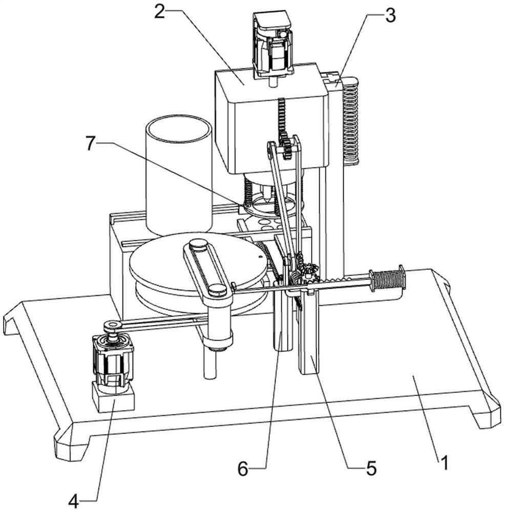
[0030] A shirt button punching device such as figure 1 As shown, it includes a base 1, a rotating mechanism 2 and an up and down mechanism 3. The rear side of the top of the base 1 is provided with a rotating mechanism 2, and the rotating mechanism 2 is provided with an up and down mechanism 3.
[0031] The staff places the button in the rotating mechanism 2, then starts the rotating mechanism 2 to work, then manually presses the upper and lower mechanism 3 downwards, so that the rotating mechanism 2 punches the button. After the punching is completed, the upper and lower mechanism 3 is released to make Turning mechanism 2 is reset, and turning mechanism 2 is closed at last, and the staff takes out the button that has punched out from turning mechanism 2.
Embodiment 2
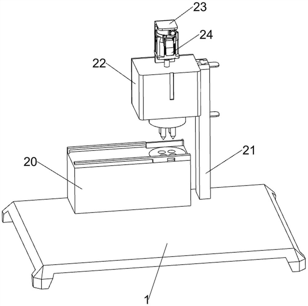
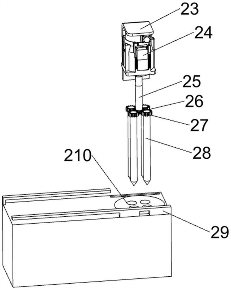
[0033] On the basis of Example 1, such as figure 2 , image 3 , Figure 4 , Figure 9 , Figure 10 and Figure 11 As shown, the rotating mechanism 2 includes a first mounting platform 20, a first pillar 21, a second mounting platform 22, a fixed assembly 23, a first servo motor 24, a first rotating shaft 25, a first spur gear 26, and a second spur gear 27. Drill bit 28, baffle plate 29 and placement platform 210, the first installation platform 20 is connected to the top rear side of the base 1, the first pillar 21 is provided on the rear side of the top of the base 1, and the second installation platform is slidably connected to the upper part of the first pillar 21. Table 22, the top of the second installation table 22 is provided with a fixed assembly 23, the inside of the fixed assembly 23 is provided with a first servo motor 24, the output end of the first servo motor 24 is connected with a first rotating shaft 25, and the first rotating shaft 25 passes through the s...
Embodiment 3
[0037] On the basis of Example 2, such as Figure 5-11 As shown, a feeding mechanism 4 is also included. The top left side of the base 1 is provided with a feeding mechanism 4. The feeding mechanism 4 includes a second pillar 40, a second servo motor 41, a third pillar 42, and a first bearing seat 43. , the second rotating shaft 44, the first belt drive assembly 45, the third rotating shaft 46, the second belt drive assembly 47, the third connection block 48, the second bearing seat 49, the fourth rotating shaft 410, the third belt drive assembly 411, the second A rotating disk 412, the second rotating disk 413, the first connecting shaft 414, the second connecting shaft 415, the first stopper 416 and the lower material bucket 417, the left front side of the top of the base 1 is provided with a second pillar 40, and the top of the second pillar 40 is provided with a second pillar 40. There is a second servo motor 41, a third pillar 42 is provided on the left part of the top of...
PUM
 Abstract
Description
Claims
Application Information
 - Generate Ideas
- Intellectual Property
- Life Sciences
- Materials
- Tech Scout
- Unparalleled Data Quality
- Higher Quality Content
- 60% Fewer Hallucinations
Browse by: Latest US Patents, China's latest patents, Technical Efficacy Thesaurus, Application Domain, Technology Topic, Popular Technical Reports.
© 2025 PatSnap. All rights reserved.Legal|Privacy policy|Modern Slavery Act Transparency Statement|Sitemap|About US| Contact US: help@patsnap.com