
Color mixing injection table of injection molding machine and injection molding machine

An injection molding machine and color mixing technology, which is applied in the field of injection molding equipment, can solve the problems of large machine footprint, change in properties, and insufficient compact structure.

Active Publication Date: 2021-03-09
广东佳明机器有限公司
View PDF4 Cites 3 Cited by
  • Summary
  • Abstract
  • Description
  • Claims
  • Application Information

AI Technical Summary

Problems solved by technology

[0002] Most of the existing mixed two-color injection molding machines are parallel double-injection table mechanisms, and the machine occupies a large area and the structure is not compact enough.
In addition, the mixed-color injection molding machine with parallel double-shot platform also has the problem of too long flow path, that is, the distance from the molten plastic leaving the barrel, through the flow path to the nozzle, and finally injected from the nozzle is too long, which is not conducive to accurate Control injection volume
In addition, if the material stays in the flow channel for too long, it may also change its properties

Method used


Image

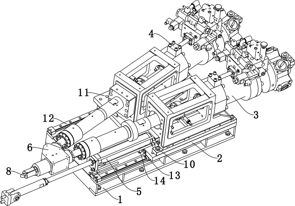
  • Color mixing injection table of injection molding machine and injection molding machine
  • Color mixing injection table of injection molding machine and injection molding machine
  • Color mixing injection table of injection molding machine and injection molding machine

Examples


Embodiment Construction

[0026] The present invention provides an injection molding machine mixed-color injection platform and an injection molding machine. In order to make the purpose, technical solution and effect of the present invention clearer and clearer, the present invention will be further described in detail below with reference to the accompanying drawings and examples. It should be understood that the specific embodiments described here are only used to explain the present invention, not to limit the present invention.

[0027] In describing the present invention, it should be understood that the terms "upper", "lower", "left", "right", "inner", "outer", etc. indicate orientation or positional relationship based on the orientation shown in the drawings Or positional relationship is only for the convenience of describing the present invention and simplifying the description, but does not indicate or imply that the referred device or element must have a specific orientation, and a specific o...


PUM


Abstract

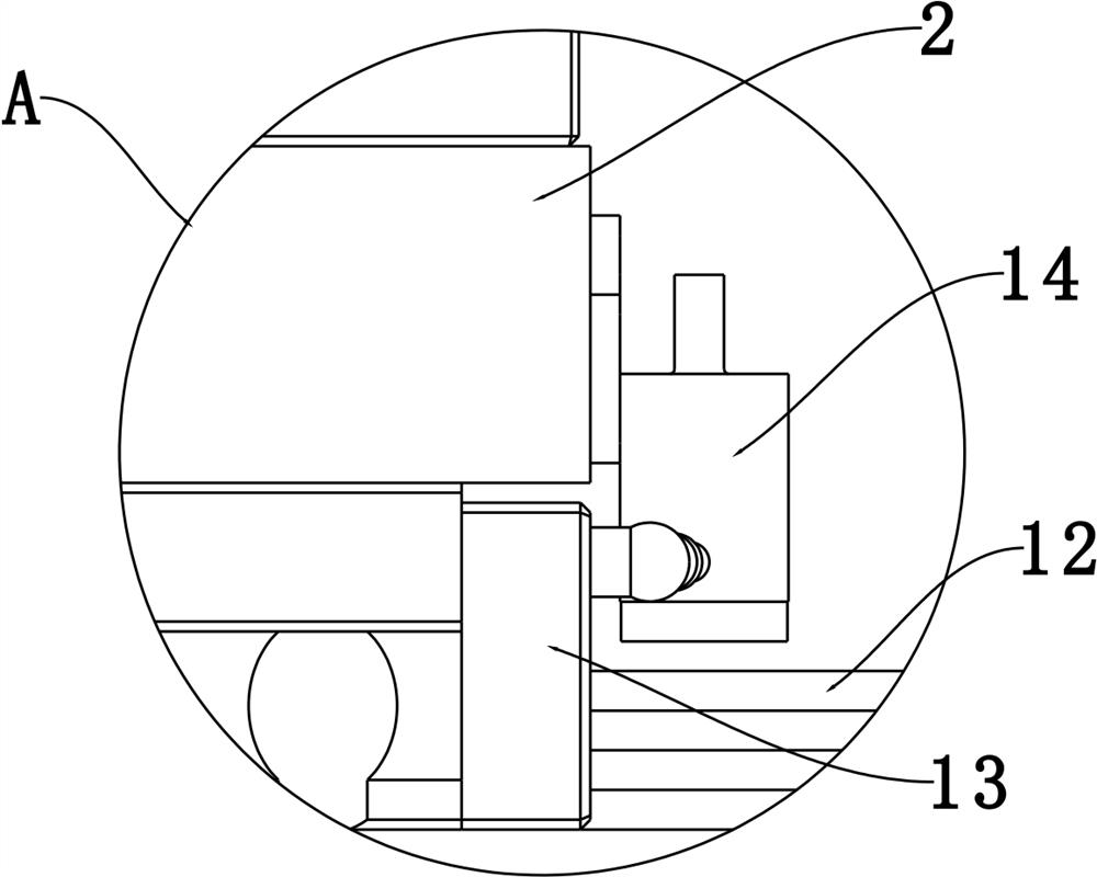
The invention discloses a color mixing injection table of an injection molding machine and the injection molding machine. The color mixing injection table comprises an injection table base, a slidingbottom plate, a main injection table mechanism, an auxiliary injection table mechanism, a movable oil cylinder mechanism, a flange connecting body, a color mixing mechanism and an injection nozzle, wherein the sliding bottom plate is connected to the injection table base in a sliding mode, the main injection table mechanism and the auxiliary injection table mechanism are fixed to the sliding bottom plate, the discharging ends of the main injection table mechanism and the auxiliary injection table mechanism are connected with the flange connecting body, and the included angle between the horizontal projection of the main injection table mechanism and the horizontal projection of the auxiliary injection table mechanism is smaller than 90 degrees. The movable oil cylinder mechanism is used for driving the sliding bottom plate to slide back and forth along the injection table base, the color mixing mechanism is arranged in the flange connecting body, the discharging end of the main injection table mechanism and the discharging end of the auxiliary injection table mechanism communicate with the feeding end of the color mixing mechanism, and the injection nozzle is connected with the discharging end of the color mixing mechanism. The color mixing injection table is compact in structure, the flowing distance of materials is short, and the change of material properties can be effectively avoided.

Description

technical field [0001] The invention relates to the technical field of injection molding equipment, in particular to an injection molding machine mixing color injection platform and an injection molding machine. Background technique [0002] Most of the existing mixed two-color injection molding machines are parallel double-injection units, and the machine occupies a large area and the structure is not compact enough. In addition, the mixed-color injection molding machine with parallel double-shot platform also has the problem of too long flow path, that is, the distance from the molten plastic leaving the barrel, through the flow path to the nozzle, and finally injected from the nozzle is too long, which is not conducive to accurate Control injection volume. In addition, if the material stays in the flow channel for too long, it may also change its properties. [0003] It can be seen that the prior art still needs to be improved and enhanced. Contents of the invention ...

Claims


Application Information

Patent Timeline
IPC IPC(8): B29C45/17B29C45/07B29C45/16
CPCB29C45/07B29C45/16B29C45/17B29C2045/1784
Inventor 李裔强甘瑞丰方来
Owner 广东佳明机器有限公司
Learn More