Engine compartment cooling device
A cooling device and engine compartment technology, applied to the cooling system of the power unit, etc., can solve the problems of increasing air resistance, high temperature, destroying the smooth and continuous characteristics of the aircraft skin, and achieving the goal of reducing air resistance and uniform temperature distribution Effect
- Summary
- Abstract
- Description
- Claims
- Application Information
AI Technical Summary
Problems solved by technology
Method used
Image

Examples
Embodiment Construction
[0030] In order to make the purpose, technical solution and advantages of the application more clear, the technical solution in the embodiment of the application will be described in more detail below in conjunction with the drawings in the embodiment of the application.
[0031] In order to overcome the defects pointed out in the prior art, the present application provides an engine compartment cooling device, which can reduce air resistance and make the air flow in the engine compartment more uniform.
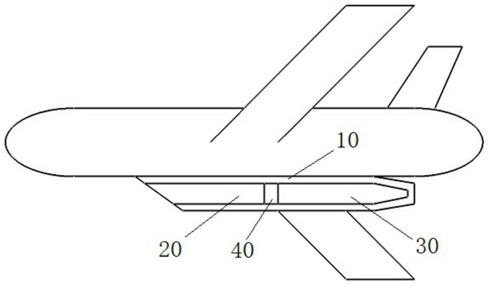
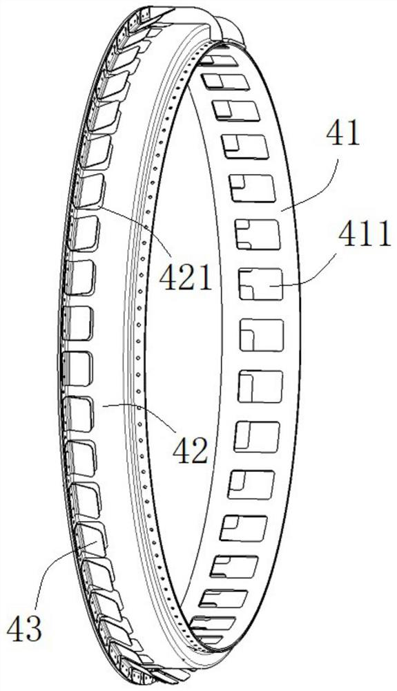
[0032] Such as figure 1 and figure 2 As shown, the engine compartment cooling device 40 provided by the present application is disposed between the intake passage 20 and the engine 30 , and the generator cooling device 40 includes a first metal ring 41 , a second metal ring 42 and a limiting plate 43 .
[0033] The first metal ring 41 can be used as a transition part between the outlet of the air inlet and the inlet of the engine, and a plurality of air inlet openings 411 a...
PUM
 Abstract
Description
Claims
Application Information
 - Generate Ideas
- Intellectual Property
- Life Sciences
- Materials
- Tech Scout
- Unparalleled Data Quality
- Higher Quality Content
- 60% Fewer Hallucinations
Browse by: Latest US Patents, China's latest patents, Technical Efficacy Thesaurus, Application Domain, Technology Topic, Popular Technical Reports.
© 2025 PatSnap. All rights reserved.Legal|Privacy policy|Modern Slavery Act Transparency Statement|Sitemap|About US| Contact US: help@patsnap.com