
Garment ironing equipment

A technology for ironing equipment and garments, which is applied to ironing boards, ironing machines, washing devices, etc., can solve the problems of inability to fold, occupy a large area, and waste space, and achieves increased practicability, reduced space occupation, and good control. Effect

Inactive Publication Date: 2021-03-09
桃江县鹏翔制衣有限公司
View PDF0 Cites 0 Cited by
  • Summary
  • Abstract
  • Description
  • Claims
  • Application Information

AI Technical Summary

Problems solved by technology

[0003] Existing ironing equipment cannot be folded when not in use, and occupies a large area, resulting in waste of space. Therefore, there is a need for a garment ironing equipment that can be folded

Method used


Image

  • Garment ironing equipment
  • Garment ironing equipment
  • Garment ironing equipment

Examples


Embodiment 1

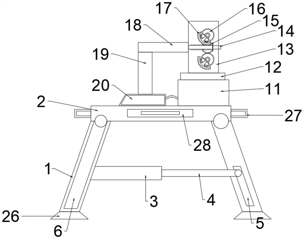
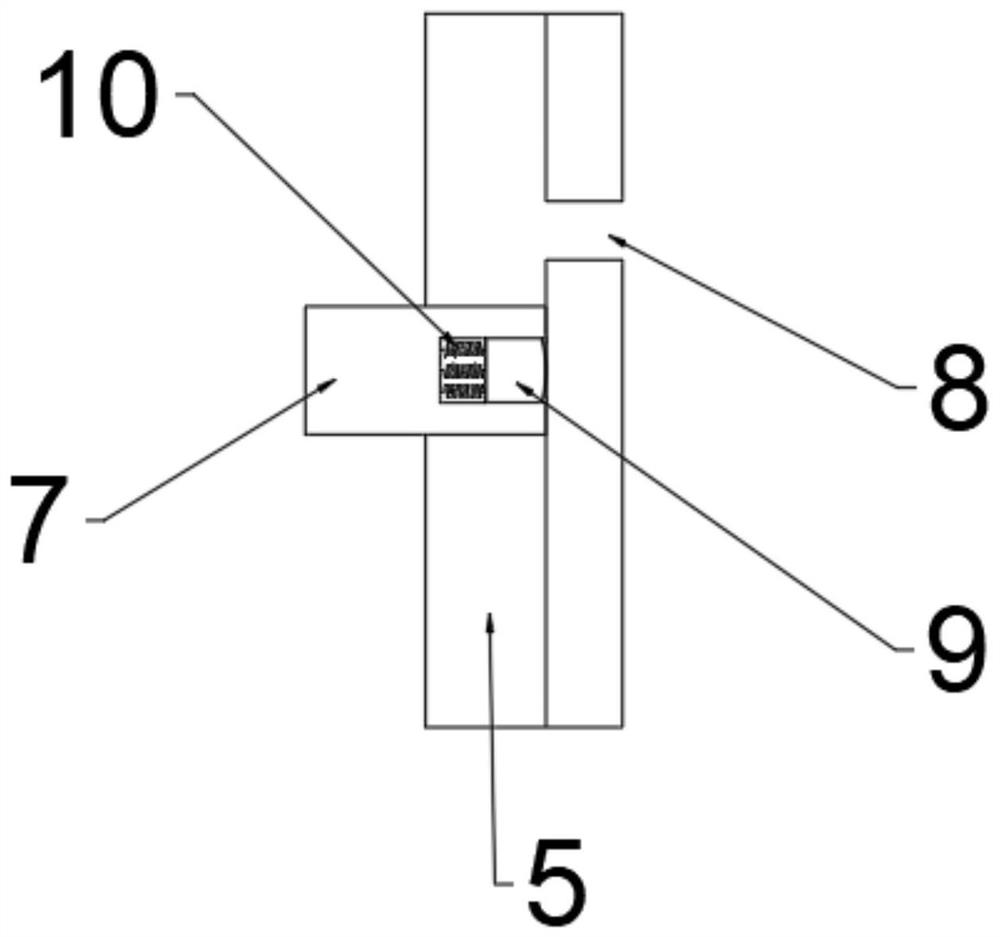
[0030] refer to Figure 1 ~ Figure 2 , an ironing device for garments, comprising an ironing board 2, legs 1 are connected by bolts at the left and right ends of the bottom of the ironing board 2, an ironing mechanism is arranged above the ironing board 2, and an ironing mechanism is arranged on the left side leg 1 There is a second chute 6, the first chute 5 is provided on the right leg 1, the rear of the left leg 1 is rotatably connected with a connecting pipe 3, and the end of the connecting pipe 3 far away from the left leg 1 is plugged and connected with a The drawing pipe 4, the left end of the ironing board 2 and the end of the drawing pipe 4 away from the connecting pipe 3 are bolted to a sliding post 7, and the first chute 5 and the second chute 6 are slidably connected to the sliding post 7. The inside of the column 7 is provided with a groove, and the limit rod 9 is slidably connected in the groove, and the end of the limit rod 9 near the groove is bolted to a sprin...

Embodiment 2

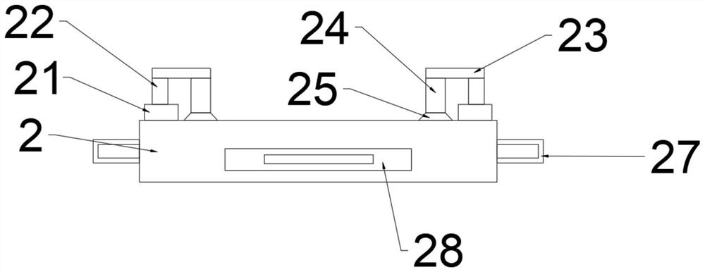
[0038] refer to Figure 3 ~ Figure 4 , an ironing device for garments. Compared with Embodiment 1, the four corners of the ironing board 2 are connected with the second hydraulic pipe 21 by bolts, and the upper part of the second hydraulic pipe 21 is connected with the second telescopic pipe. 22. The end of the second telescopic tube 22 away from the second hydraulic tube 21 is bolted to the second connecting plate 23, and the bottom of the second connecting plate 23 away from the second telescopic tube 22 is bolted to the second connecting rod 24. The second connection One end bolt of the rod 24 away from the second connecting plate 23 is connected with a pressing plate 25, the pressing plate 25 is disc-shaped, when the clothes are put into the top of the ironing board 2, the second hydraulic pipe 21 is activated, so that the first Two telescoping tubes 22 drive the second connecting plate 23 to move down, and then the second connecting rod 24 drives the pressing plate 25 to ...


PUM


Abstract

The invention discloses garment ironing equipment. The garment ironing equipment comprises an ironing plate, supporting legs are arranged at the left end and the right end of the lower part of the ironing plate, an ironing mechanism is arranged above the ironing plate, a second sliding groove is formed in the left supporting leg, a first sliding groove is formed in the right supporting leg, a connecting pipe is arranged behind the left supporting leg, a drawing pipe is arranged at the end, away from the left supporting leg, of the connecting pipe, sliding columns are arranged at the left end of the ironing plate and the end, away from the connecting pipe, of the drawing pipe, and the first sliding groove and the second sliding groove are slidably connected with the sliding columns. When the garment ironing equipment is unfolded, the right supporting leg is fixed, the left supporting leg is pulled, a limiting rod can be clamped in a limiting hole under the action of a spring, and garment can be placed on the upper part of the ironing plate and ironed through the ironing mechanism; and when the garment ironing equipment is stored, only the limiting rod needs to be pressed, so that the limiting rod is disengaged from the limiting hole, the sliding columns can slide in the first sliding groove and the second sliding grooves to be folded and stored, the occupied space is reduced, and the garment ironing equipment is suitable for large-scale popularization.

Description

technical field [0001] The invention relates to the technical field of garments, in particular to a garment ironing device. Background technique [0002] Ready-made clothing refers to finished clothes produced in batches according to certain specifications and size standards. It is a concept that appears relative to tailor-made and self-made clothes. As an industrial product, ready-made garments conform to the economic principles of mass production, with mechanized production, serialized product scale, standardized quality, and unified packaging, with labels such as brand, fabric composition, size, and washing and maintenance instructions. [0003] Existing ironing equipment cannot be folded when not in use, and occupies a large area, resulting in waste of space. Therefore, there is a need for a ready-made garment ironing equipment that can be folded. Contents of the invention [0004] The purpose of the present invention is to solve the shortcomings in the prior art, and...

Claims


Application Information

Patent Timeline
IPC IPC(8): D06F81/02D06F69/00
CPCD06F69/00D06F81/02
Inventor 高细
Owner 桃江县鹏翔制衣有限公司
Learn More