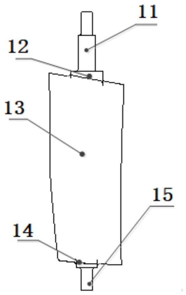
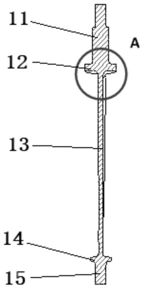
Composite material adjustable stator blade

A technology for composite materials and stator adjustment, which is applied in liquid fuel engines, components of pumping devices for elastic fluids, non-variable pumps, etc., and can solve the complex stress and structural configuration of adjustable stator blades , Composite material layering direction changes drastically, etc., to solve the design feasibility and engineering problems, solve the complex configuration, and improve the ability to resist aerodynamic bending moment and aerodynamic torque

Active Publication Date: 2021-03-09
AECC SHENYANG ENGINE RES INST
View PDF7 Cites 2 Cited by
  • Summary
  • Abstract
  • Description
  • Claims
  • Application Information

AI Technical Summary

Problems solved by technology

[0003] At present, resin-based composite materials are mainly used in aero-engine components such as external culvert casings, fan rotor blades, and stator segments (non-adjustable). Single, simple transfer structure, etc.
[0004] However, for compressor/fan adjustable stator blades, its structural configuration is complex, the direction of composite material layup changes drastically, and its load and service conditions are more complicated than those of outer casing, fan rotor blades and stator segments.
[0005] However, the existing structural forms of composite engine components are difficult to meet the strength requirements and use requirements of the adju

Method used


Image

  • Composite material adjustable stator blade
  • Composite material adjustable stator blade
  • Composite material adjustable stator blade

Examples


Embodiment Construction

[0041] In order to make the purpose, technical solution and advantages of the application more clear, the technical solution in the embodiment of the application will be described in more detail below in conjunction with the drawings in the embodiment of the application. In the drawings, the same or similar reference numerals denote the same or similar elements or elements having the same or similar functions throughout. The described embodiments are some, but not all, embodiments of the application. The embodiments described below by referring to the figures are exemplary, and are intended to explain the present application, and should not be construed as limiting the present application. Based on the embodiments in this application, all other embodiments obtained by persons of ordinary skill in the art without creative efforts fall within the protection scope of this application. Embodiments of the present application will be described in detail below in conjunction with th...


PUM


Abstract

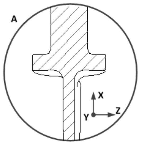
The invention belongs to the technical field of engine maintenance equipment design, and particularly relates to a composite material adjustable stator blade which comprises an upper shaft neck, a lower shaft neck, an upper marginal plate, a lower marginal plate, and a blade body; besides, the blade is divided into a central layer plate area, a central filling area, a reinforced layer plate area and a molded surface structure area, the central layer plate area and the reinforced layer plate area are composed of laminated plates formed by laying composite material prepregs, the central fillingarea is composed of composite material prepregs, and the molded surface structure area is composed of resin or single-layer prepregs covering the surface of the molded surface structure area; and thecentral layer plate area and the central filling area form a core bearing area of the blade, the reinforced layer plate area is located on the two sides of the core bearing area, and the molded surface structure area is used for ensuring that the composite material adjustable stator blade is smooth in appearance. According to the composite material adjustable stator blade, the design feasibility and engineering problems of the composite material adjustable stator blade are effectively solved, the problems that the blade configuration is complex, and layering is difficult to achieve are effectively solved, and the pneumatic bending moment and pneumatic torque resistance of the composite material adjustable stator blade is improved.

Description

technical field [0001] The application belongs to the technical field of engine maintenance equipment design, and in particular relates to an adjustable stator vane made of composite material. Background technique [0002] Resin-based composite material blades are widely used in aero-engines. A lot of research has been carried out on composite materials abroad. At present, composite material blades have been applied to GE90, GEnx, TRENT1000, TRENTXWB and LEAP-X and other engines. Compared with titanium alloy blades, composite material fan blades have the characteristics of light weight, high efficiency and low noise, and have better anti-flutter performance and damage tolerance capabilities. At the same time, the anti-bird strike performance can also meet airworthiness requirements. [0003] At present, resin-based composite materials are mainly used in aero-engine components such as external culvert casings, fan rotor blades, and stator segments (non-adjustable). Single, s...

Claims


Application Information

Patent Timeline
IPC IPC(8): F04D29/56F04D29/54F04D29/02
CPCF04D29/563F04D29/544F04D29/023Y02E10/72
Inventor 曹铁男宋旭圆杨吉星
Owner AECC SHENYANG ENGINE RES INST
Why Eureka
Try Eureka