Double-flap-valve discharging structure for cyclone of spray dryer

A technology of spray dryer and flap valve, which is applied in the direction of lifting valve, valve detail, conveyor, etc., can solve the problems of fan stuck, unable to close tightly, butterfly valve blocked, etc., and achieves easy operation, high degree of automation, Good sealing effect

Pending Publication Date: 2021-03-09
CHANGZHOU YIBU DRYING EQUIP
View PDF0 Cites 6 Cited by
  • Summary
  • Abstract
  • Description
  • Claims
  • Application Information

AI Technical Summary

Problems solved by technology

[0003] In order to solve the problem in the prior art that the fan at the cyclone outlet is stuck by the material or the butterfly valve is blocked by the material and cannot be closed tightly, resulting in air leakage, the invention provides a double flap valve discharge valve for the cyclone of the spray dryer. structure

Method used


Image

  • Double-flap-valve discharging structure for cyclone of spray dryer
  • Double-flap-valve discharging structure for cyclone of spray dryer
  • Double-flap-valve discharging structure for cyclone of spray dryer

Examples


Embodiment 1

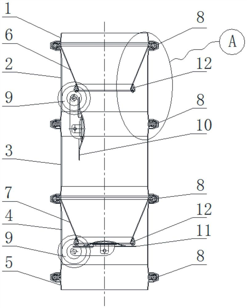
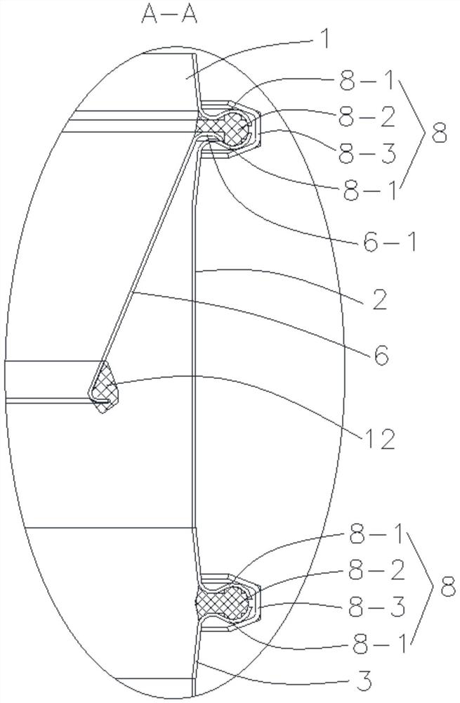
[0019] Such as Figure 1~3 As shown, a double flap valve discharge structure for the spray dryer cyclone, including the upper end 1, the first cylinder 2, the second cylinder 3, the third cylinder 4 and the The lower end 5, between the upper end 1 and the first cylinder 2, between the first cylinder 2 and the second cylinder 3, between the second cylinder 3 and the third cylinder 4, and the third cylinder Both the body 4 and the lower end 5 are fixedly connected by a sealing connector 8, an upper cone bucket 6 is arranged inside the first cylinder body 2, a lower cone bucket 7 is arranged inside the third cylinder body 4, and the upper end The head 1, the upper cone 6, the first cylinder 2, the second cylinder 3, the lower cone 7, the third cylinder 4 and the lower end 5 are connected in sequence, and the upper cone 6 and the lower cone 7 The direction of the material is consistent, and its big end is set upward, which is convenient for material collection and improves the ef...


PUM


Abstract

The invention belongs to the technical field of spray dryers, and especially relates to a double-flap-valve discharging structure for cyclone of a spray dryer. The double-flap-valve discharging structure for the cyclone of the spray dryer comprises an upper end head, a first barrel body, a second barrel body and a third barrel body which are sequentially arranged from top to bottom, wherein the upper end head and the first barrel body are fixedly connected through a sealing connecting piece, the first barrel body and the second barrel body are fixedly connected through a sealing connecting piece, and the first barrel body and the third barrel body are fixedly connected through a sealing connecting piece; an upper conical hopper is arranged in the first barrel body; a lower conical hopper is arranged in the third barrel body; and the upper end head, the upper conical hopper, the first barrel body, the second barrel body, the lower conical hopper and the third barrel body are sequentially communicated. The discharging structure further comprises an upper driving mechanism, an upper valve plate, a lower driving mechanism and a lower valve plate, wherein the upper driving mechanism isused for driving the upper valve plate to move close to or away from the bottom end of the upper conical hopper; a valve plate sealing ring is arranged between the upper valve plate and the bottom endof the upper conical hopper; the lower driving mechanism is used for driving the lower valve plate to move close to or away from the bottom end of the lower conical hopper; and a valve plate sealingring is also arranged between the lower valve plate and the bottom end of the lower conical hopper.

Description

technical field [0001] The invention belongs to the technical field of spray dryers, and in particular relates to a double-flap valve discharge structure used for the cyclone of the spray dryer. Background technique [0002] The most commonly used method of collecting materials for spray dryers is cyclone collection. The cyclone outlet is generally in a negative pressure state. Now, it is generally used to discharge the material in the form of a closed fan or a double butterfly valve to avoid the collusion between the cyclone and the external air. For some materials that are easy to absorb moisture or have poor fluidity, it often occurs that the shut-off fan is stuck by the material or the butterfly valve is blocked by the material and cannot be closed tightly, resulting in air leakage, which causes a lot of trouble for the discharge. Contents of the invention [0003] In order to solve the problem in the prior art that the fan at the cyclone discharge port is stuck by the...

Claims


Application Information

Patent Timeline
Patent Type & Authority Applications(China)
IPC IPC(8): F16K1/22F16K1/226F16K31/122B65G53/46
CPCB65G53/4608F16K1/221F16K1/223F16K1/226F16K1/2263F16K31/122
Inventor 范文国查国才
Owner CHANGZHOU YIBU DRYING EQUIP
Why Eureka
Try Eureka