Valve sound wave monitoring system and method
A technology for monitoring systems and valves, applied to valve devices, engine components, mechanical equipment, etc., can solve problems such as the inability to monitor valves in underground fluid pipelines, and achieve the effects of low cost, low failure rate, and high detection rate
- Summary
- Abstract
- Description
- Claims
- Application Information
AI Technical Summary
Problems solved by technology
Method used
Image
Examples
Embodiment 1
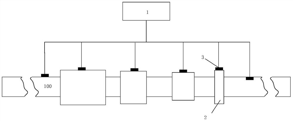
[0037] see figure 1 As shown, the present invention provides a valve acoustic monitoring system, comprising:
[0038] Valve 2; the valves are installed in the fluid pipeline 100 at intervals;
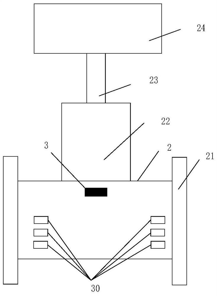
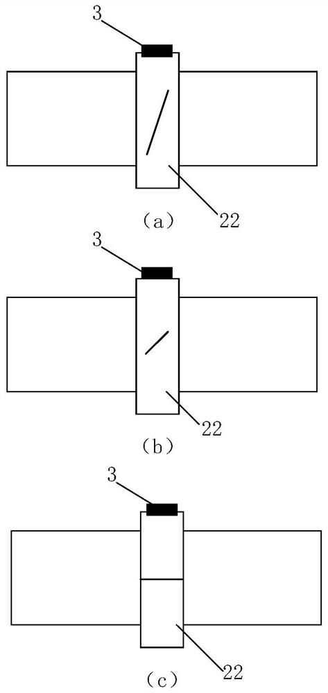
[0039] Acoustic wave sensor 3, at least one acoustic wave sensor is installed at each valve place; Acoustic wave sensor is arranged on the inside or outside of the valve close to the spool; Corresponding to geographic information coding; when the acoustic wave sensor transmits the collected acoustic wave signal, geographic information coding information and model information of the corresponding valve are added at the same time.
[0040] The signal transmission device is used to receive the acoustic wave signal collected by the acoustic wave sensor and send it to the acoustic wave data analysis platform;
[0041] The acoustic wave data analysis platform 1 is set in the remote monitoring room and connected to the signal transmission device through wired or wireless means; the acoustic ...
Embodiment 2
[0047] The present invention also provides a valve acoustic monitoring method, which specifically includes the following steps:
[0048] S1: Install an acoustic wave sensor at the valve position of the fluid pipeline;
[0049] S2: Encoding geographic information on each valve device equipped with an acoustic sensor;
[0050] S3: The acoustic wave sensor transmits the collected acoustic wave signal to the acoustic wave monitoring and analysis platform through the signal transmission device;
[0051] S4: Output the analysis results of the sound wave monitoring and analysis platform to the computer simulation model of the pipeline or pipe network with geographic information data, and visually display the sound wave monitoring results of the valve in the form of a pipe network simulation diagram;
[0052]S5: The acoustic wave monitoring and analysis platform uses the continuously recorded acoustic wave signal to correlate with the operating status information of the corresponding...
Embodiment 3
[0054] The present invention also provides a valve acoustic wave monitoring method for monitoring valve flow, which specifically includes:
[0055] S11: Install the valve and its acoustic wave sensor on the flow calibration experiment platform;
[0056] S12: Debug the valve and its various sensors and the data acquisition system of the flow calibration experiment platform, so as to achieve the acquisition of the acoustic signal of the qualified acoustic sensor that removes noise interference and meet the calibration requirements;
[0057] S13: Debug the pressure sensors before and after the valve, and calibrate the flow sensor of the experimental platform to meet the calibration requirements;
[0058] S14: Under different pre-valve pressures and different regulating valve flow conditions, monitor the acoustic wave signal collected by the valve acoustic wave sensor; the acoustic wave signal includes acoustic wave frequency, acoustic wave intensity, acoustic wave pressure, and a...
PUM
 Abstract
Description
Claims
Application Information
 - R&D
- Intellectual Property
- Life Sciences
- Materials
- Tech Scout
- Unparalleled Data Quality
- Higher Quality Content
- 60% Fewer Hallucinations
Browse by: Latest US Patents, China's latest patents, Technical Efficacy Thesaurus, Application Domain, Technology Topic, Popular Technical Reports.
© 2025 PatSnap. All rights reserved.Legal|Privacy policy|Modern Slavery Act Transparency Statement|Sitemap|About US| Contact US: help@patsnap.com


