Steam recovery heat exchange unit for aerated concrete industry

A technology of aerated concrete and heat exchange unit, which is applied to indirect heat exchangers, heat exchanger types, lighting and heating equipment, etc. Efficiency compensation, reduction of guiding energy consumption, and improvement of steam activity

Active Publication Date: 2022-03-18
山东汉华工业设备有限公司
View PDF8 Cites 0 Cited by
  • Summary
  • Abstract
  • Description
  • Claims
  • Application Information

AI Technical Summary

Problems solved by technology

[0003] The steam adding block in the prior art cannot effectively recycle the used steam in a timely and effective manner during actual construction, resulting in a huge waste of steam, and the recovery heat exchange unit in the prior art cannot be flexibly applied in The construction site provides users with steam transmission, which greatly increases the extra power of steam transmission, which can easily lead to excessive energy consumption, so it cannot meet the needs of existing technologies

Method used


Image

  • Steam recovery heat exchange unit for aerated concrete industry
  • Steam recovery heat exchange unit for aerated concrete industry
  • Steam recovery heat exchange unit for aerated concrete industry

Examples


Embodiment 1

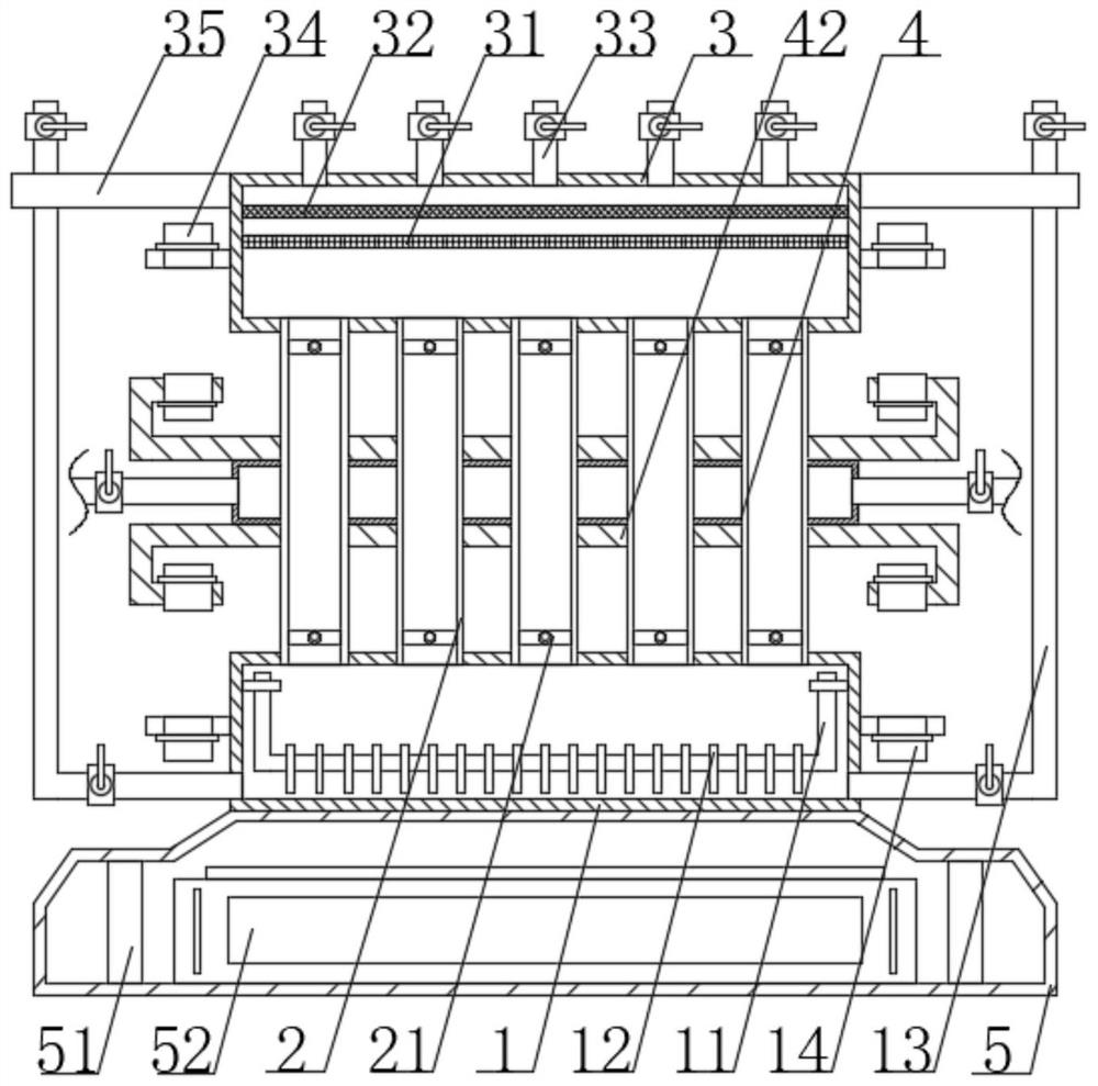
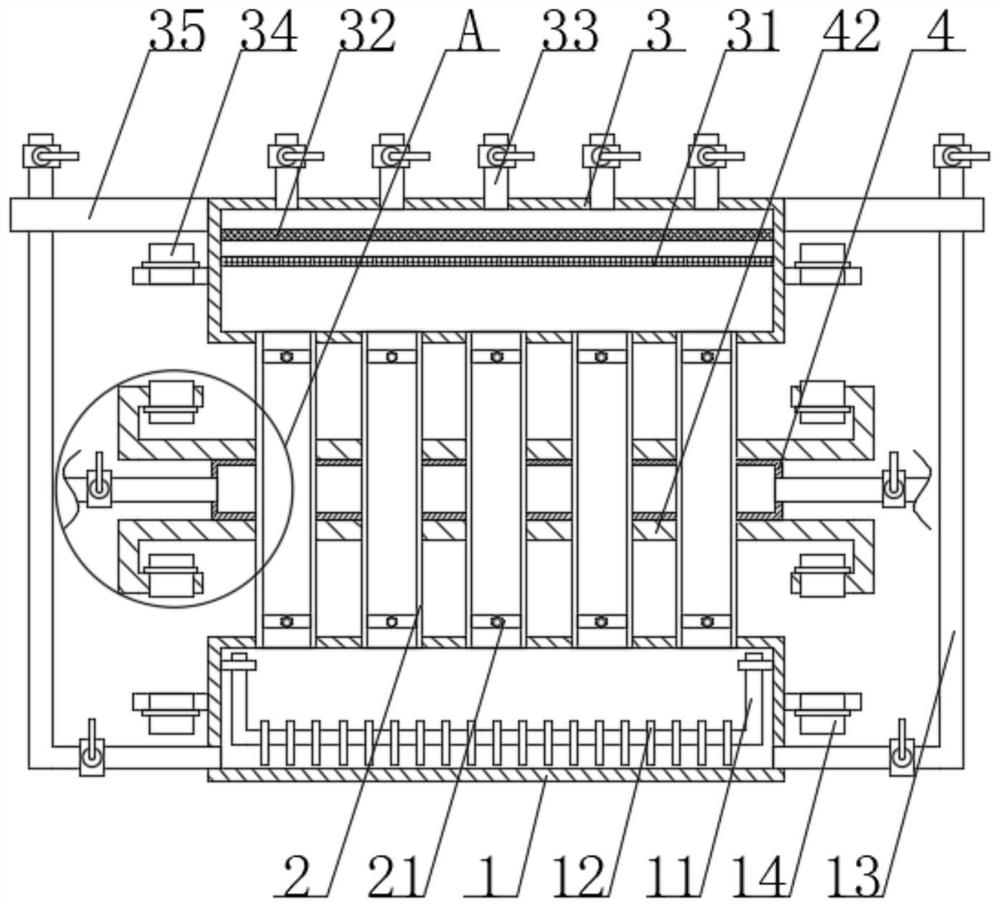
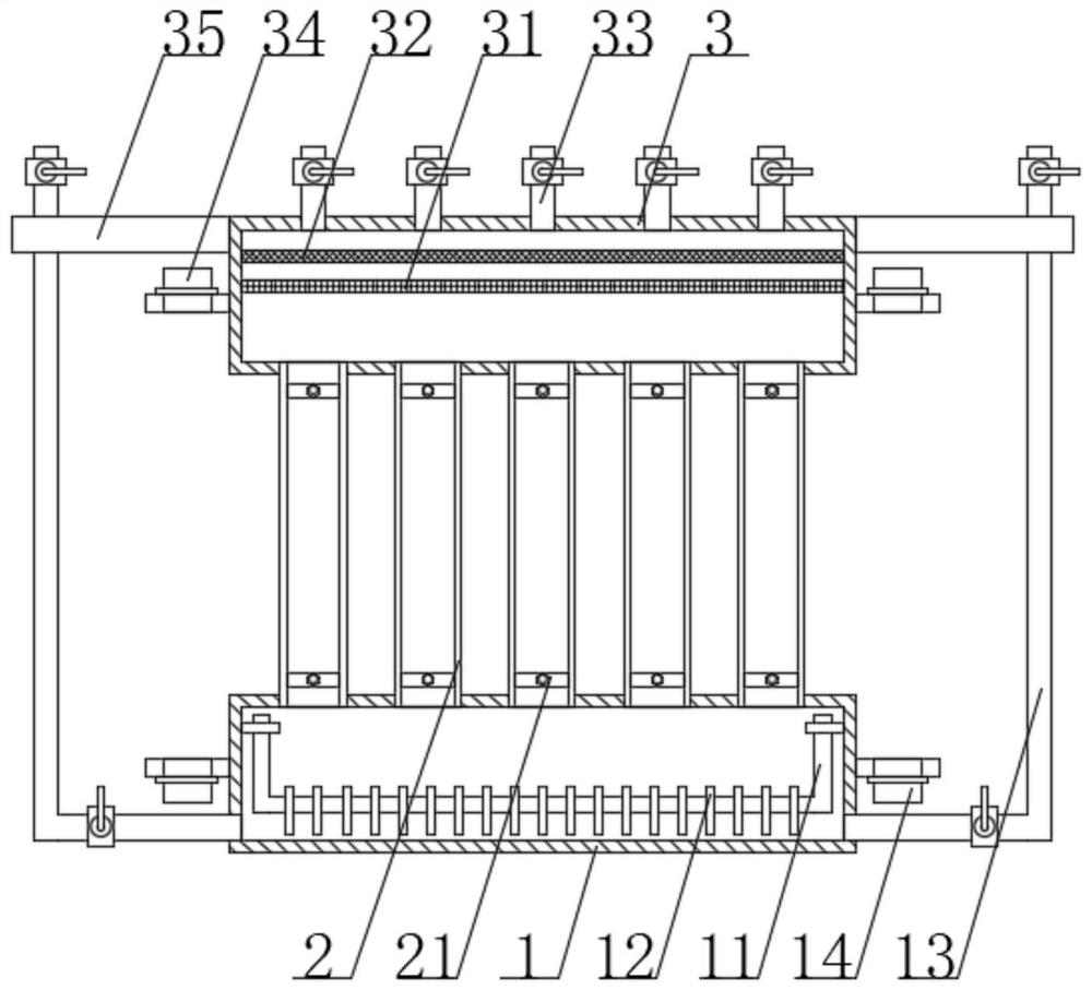
[0026] see Figure 1-6, the present invention provides a technical solution: a steam recovery heat exchange unit in the aerated concrete industry, including a storage box 1, a heat exchange tube 2 and a collection box 3, and the two sides of the inner wall of the storage box 1 close to the top are fixedly connected with heating The heater 11 has a U-shaped structure, and there are three heaters 11, and the distance between any two adjacent heaters 11 is the same, and the three heaters 11 can effectively The gas-liquid in the storage box 1 is heated to increase the activity of the gas-liquid molecules, so that the liquid is converted into a gas, and the activity of the gas is further improved. The middle parts on both sides of the outer periphery of the storage box 1 are connected to the bottom by bolts and the method. The blue is fixedly connected with a delivery pipe 13, the delivery pipe 13 is in an L-shaped structure, the lower surface of the delivery pipe 13 and the lower ...

Embodiment 2

[0028] see Figure 1-6 , the present invention provides a technical solution: a steam recovery heat exchange unit in the aerated concrete industry, including a storage box 1, a heat exchange tube 2 and a collection box 3, and the two sides of the inner wall of the storage box 1 close to the top are fixedly connected with heating The heater 11 has a U-shaped structure, and there are three heaters 11, and the distance between any two adjacent heaters 11 is the same, and the three heaters 11 can effectively The gas-liquid in the storage box 1 is heated to increase the activity of the gas-liquid molecules, so that the liquid is converted into a gas, and the activity of the gas is further improved. The middle parts on both sides of the outer periphery of the storage box 1 are connected to the bottom by bolts and the method. The blue is fixedly connected with a delivery pipe 13, the delivery pipe 13 is in an L-shaped structure, the lower surface of the delivery pipe 13 and the lower...

Embodiment 3

[0030] see Figure 1-6, the present invention provides a technical solution: a steam recovery heat exchange unit in the aerated concrete industry, including a storage box 1, a heat exchange tube 2 and a collection box 3, and the two sides of the inner wall of the storage box 1 close to the top are fixedly connected with heating The heater 11 has a U-shaped structure, and there are three heaters 11, and the distance between any two adjacent heaters 11 is the same, and the three heaters 11 can effectively The gas-liquid in the storage box 1 is heated to increase the activity of the gas-liquid molecules, so that the liquid is converted into a gas, and the activity of the gas is further improved. The middle parts on both sides of the outer periphery of the storage box 1 are connected to the bottom by bolts and the method. The blue is fixedly connected with a delivery pipe 13, the delivery pipe 13 is in an L-shaped structure, the lower surface of the delivery pipe 13 and the lower ...


PUM


Abstract

The invention discloses a steam recovery heat exchange unit in the aerated concrete industry, which includes a storage box, a heat exchange tube and a collection box. The two sides of the inner wall of the storage box near the top are fixedly connected with heaters by bolts, and the two sides of the outer periphery of the storage box are The middle part near the bottom is fixedly connected with the delivery pipe by bolts and flanges; when the controller activates the electromagnetic valve on the top of the heat exchange tube, the present invention can effectively accelerate the steam rising, so as to transport the steam to the outside through the collection box and the transmission pipe for the user. The transmission power when recovering steam can effectively reduce the guiding energy consumption during steam transmission, so that the user can actually use the steam block to recover steam for secondary use, and the transmission power can be more sufficient. At the same time, by adjusting the position of the heat exchange box It can effectively provide the required driving force for the user when transporting the steam block material, so that it is convenient for the user to be more portable and flexible when actually using the steam block to implement construction, and thus effectively improves the operation efficiency of the steam block construction.

Description

technical field [0001] The invention relates to the technical field of heat exchange units, in particular to steam recovery heat exchange units in the aerated concrete industry. Background technique [0002] Aerated blocks generally refer to aerated concrete blocks. Aerated concrete blocks are a new type of building material that is lightweight, porous, thermal insulation, good fire resistance, nailable, sawable, planable, and has a certain earthquake resistance. In the early 1930s, China began to produce this product, and it is widely used in high-rise frame structure buildings. It is an excellent new building material and has the advantages of environmental protection. The actual application of the steam block consumes a lot of energy. Steam recovery and reuse of steam is an important means of saving steam resources, but there are still many deficiencies in the actual application of steam recovery heat exchange units for steam adding blocks in the prior art, such as: [0...

Claims


Application Information

Patent Timeline
Patent Type & Authority Patents(China)
IPC IPC(8): F28D7/00F28F27/02
CPCF28D7/00F28F27/02
Inventor 郭通
Owner 山东汉华工业设备有限公司
Why Eureka
Try Eureka