Tensile shear strength test device

A tensile shear strength and testing device technology, applied in the field of testing devices, can solve problems such as large error in testing results, invalid testing results, and damage to test pieces, and achieve the effects of avoiding deviation, simple and convenient operation, and simple structure

Active Publication Date: 2021-03-09
CHINA HELICOPTER RES & DEV INST
View PDF5 Cites 0 Cited by
  • Summary
  • Abstract
  • Description
  • Claims
  • Application Information

AI Technical Summary

Problems solved by technology

[0003] 1) The force-bearing surface of the upper bonding plate has poor fit with the loading surface of the transfer fixture, resulting in large errors in the test results;
[0004] 2) The connection between the lower bonding plate and the chuck of the testing machine is a rigid connection. When clamping, it is easy to cause the test piece to be damaged in advance by torsion or bending, resulting in invalid test results

Method used


Image

  • Tensile shear strength test device
  • Tensile shear strength test device
  • Tensile shear strength test device

Examples


Embodiment Construction

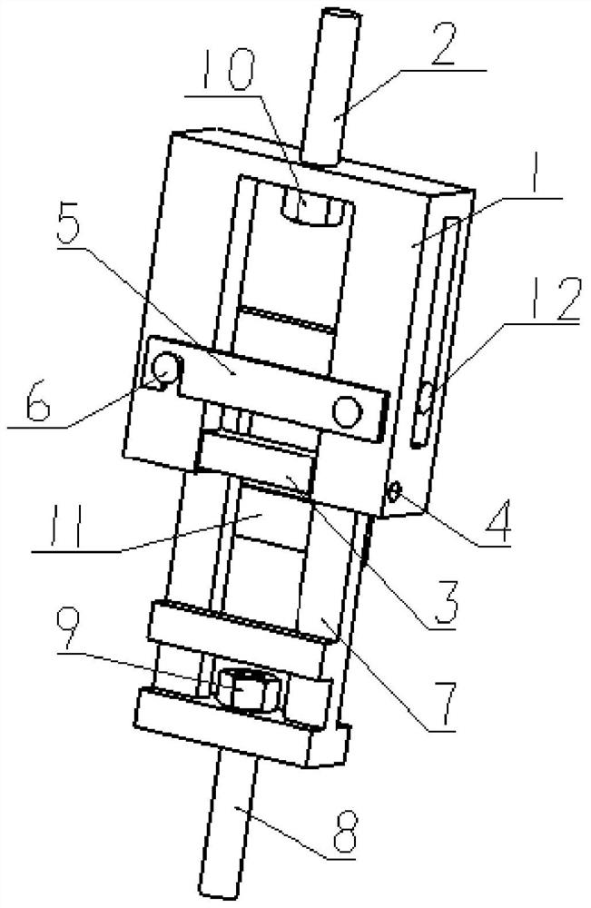
[0036] A tensile shear strength testing device, such as figure 2 As shown, the material is alloy structural steel. The device includes: sample fixing upper frame 1, upper clamping rod 2, upper loading surface of sample 3, fixing pin 4 of upper loading surface, upper baffle plate 5, screw 6, sample Fix the lower frame 7, the lower clamping rod 8, the first nut 9, the second nut 10, the lower baffle plate 11, and the fixing pin 12 of the lower loading surface.

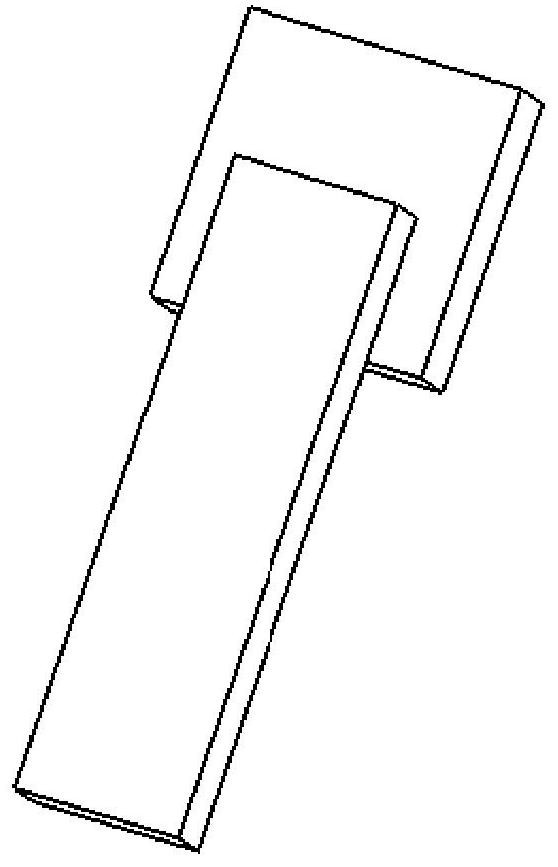
[0037] The upper frame is a rectangular frame without a bottom beam, such as image 3 Shown; There are chute in the left and right side walls of the upper frame;

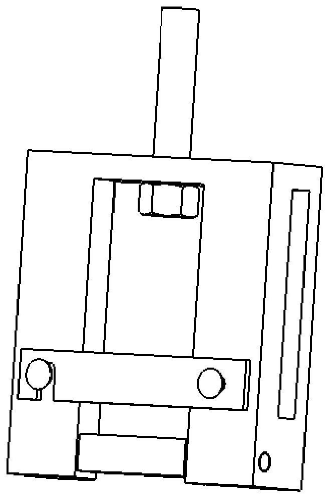
[0038] The lower frame is a rectangular frame, such as Figure 4 As shown; the lower frame is arranged between the left and right side walls of the upper frame; the left and right ends of the top beam of the lower frame are provided with first threaded holes;

[0039] One end of the fixing pin on the lower loading surface is processed with external thread,...


PUM


Abstract

The invention belongs to the technical field of detection devices, and discloses a tensile shear strength test device. A sample fixing upper frame is connected with an upper clamping rod with a threadand is locked by a nut. A sample upper loading surface with threaded holes at two ends is connected with the sample fixing upper frame through an upper loading surface fixing pin. An upper baffle plate is arranged on the sample fixing upper frame through two screws. One end of the sample fixing lower frame is installed in guide grooves in the two sides of the sample fixing upper frame through twolower loading face fixing pins with threads, and the other end of the sample fixing lower frame is connected with a lower clamping rod with threads and locked through a nut. The lower baffle plate isarranged on the sample fixing lower frame through two screws. The sample is in a free state before being loaded so that the sample is prevented from being damaged in advance due to abnormal externalforce in the test clamping process, and the detection accuracy and reliability are ensured.

Description

technical field [0001] The invention belongs to the technical field of detection devices, in particular to a tensile shear strength test device. Background technique [0002] The bonding strength between the armored seat bulletproof ceramic sheet and the carbon fiber seat pan is one of the important evaluation indicators for the safety performance of the seat. In order to monitor the bonding strength index of the seat, a small sample of the same material is selected, and it is the same The furnace test piece made by the bonding process is tested for tensile shear strength to evaluate the bonding strength of the seat to ensure the safety performance of the seat. A typical tensile shear specimen such as figure 1 shown. At present, the method used to test the shear strength of tensile shear samples is that the upper bonding plate is connected to the testing machine after being transferred by the clamp, and the lower bonding plate is directly connected to the chuck of the test...

Claims


Application Information

Patent Timeline
Patent Type & Authority Applications(China)
IPC IPC(8): G01N19/04
CPCG01N19/04
Inventor 刘冲高彩虹陶冠舟
Owner CHINA HELICOPTER RES & DEV INST
Why Eureka
Try Eureka