
Fuel plate surface pollution positioning and detecting device and system

A positioning detection device and surface contamination technology, applied in the field of nuclear detection, can solve the problems of low detection efficiency and low degree of automation, and achieve the effect of high detection efficiency, high degree of automation, and large measurement area

Active Publication Date: 2021-03-09
NUCLEAR POWER INSTITUTE OF CHINA
View PDF21 Cites 0 Cited by
  • Summary
  • Abstract
  • Description
  • Claims
  • Application Information

AI Technical Summary

Problems solved by technology

[0005] In order to solve the technical problems of low detection efficiency and low degree of automation of the existing fuel plate surface pollution detection technology, the present invention provides a fuel plate surface pollution positioning detection device

Method used


Image

  • Fuel plate surface pollution positioning and detecting device and system
  • Fuel plate surface pollution positioning and detecting device and system
  • Fuel plate surface pollution positioning and detecting device and system

Examples


Embodiment 1

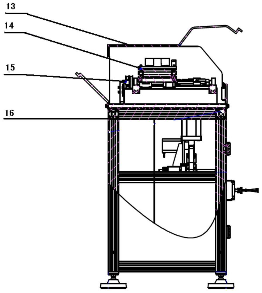
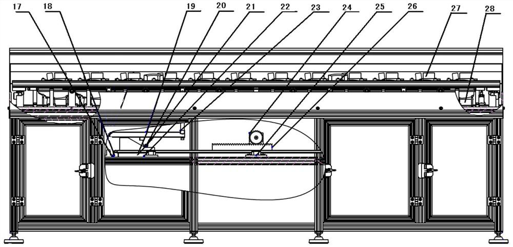
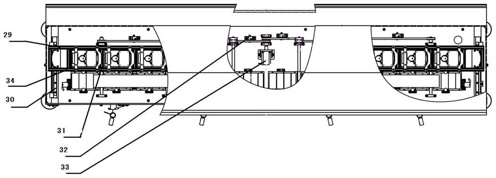
[0033] This embodiment proposes a fuel plate surface pollution location detection device, such as Figure 1-3 As shown, the fuel plate surface contamination location detection device includes: the detection device includes a shield 13, an upper surface detection unit 27, a lower surface detection unit 28, a lifting unit, a workpiece transfer unit and a support mechanism 16; wherein the shield 13 It is fixed on the support mechanism 16 and forms a cavity with the support mechanism 16 to accommodate the upper surface detection unit 27 , the lower surface detection unit 28 , the lifting unit and the workpiece transfer unit arranged on the support mechanism 16 . For the convenience of subsequent description, this embodiment refers to figure 2 front view of and image 3 In the top view of the support mechanism, the left-right direction (ie, the length direction) of the support mechanism is defined as the transverse direction, and the front-to-back direction (ie, the width directi...

Embodiment 2

[0043] Based on the fuel plate surface pollution location detection device proposed in the above embodiment 1, this embodiment proposes a fuel plate surface pollution location detection system, such as Figure 4 Said, the detection system includes a signal processing device 5, a host computer 7, a power supply device 1 and a fuel plate surface contamination location detection device 3 (that is, the fuel plate surface contamination location detection device proposed in the above-mentioned embodiment 1); the power supply device 1 Power supply for the signal processing device 5, the upper computer 7 and the fuel plate surface contamination location detection device 3 respectively; The processing device 5 is connected in communication.

[0044] Specifically, in this embodiment, the power supply device 1 adopts a regulated power supply, and the host computer adopts a computer; the regulated power supply 1 is connected to the surface pollution detection device 3 through the power co...


PUM


Abstract

The invention discloses a fuel plate surface pollution positioning and detecting device and system. The fuel plate surface pollution positioning and detecting device comprises a shielding cover, an upper surface detecting unit, a lower surface detecting unit, a lifting unit, a workpiece conveying unit and a supporting mechanism. The shielding cover is fixed on the supporting mechanism, and the shielding cover and the supporting mechanism form a cavity so as to accommodate the upper surface detecting unit, the lower surface detecting unit, the lifting unit and the workpiece conveying unit whichare arranged on the supporting mechanism. When fuel plate surface pollution detection is carried out, a fuel element is placed on the auxiliary supporting mechanism of the detection device, a detection equipment box body is closed, the workpiece conveying mechanism is started, the fuel element is conveyed to a detection initial position, and after the fuel element is in place, the detecting unitsare started for detection. The device is high in automation degree, large in detection area, low in failure rate and high in safety coefficient, can achieve accurate positioning and detecting of pollution points, facilitates cleaning of surface pollution, and avoids secondary pollution.

Description

technical field [0001] The invention relates to the technical field of nuclear detection, in particular to a device and system for locating and detecting contamination on the surface of a fuel plate. Background technique [0002] Fuel plates have been widely used due to their excellent properties. However, in the development process of the fuel plate, in order to ensure the manufacturing quality and prevent possible spread of nuclear pollution, it is necessary to detect the amount of uranium contamination on the surface of the nuclear fuel plate. Moreover, in order to confirm the location of the pollution point, facilitate cleaning and reduce the secondary transmission of pollution, it is particularly important to locate and detect the surface pollution point. Therefore, it is of great significance to complete the detection and location of fuel plate surface contamination for the development and production of fuel plates. [0003] At present, the detection of surface conta...

Claims


Application Information

Patent Timeline
Patent Type & Authority Applications(China)
IPC IPC(8): G01T1/169G01T1/20G01T7/02
CPCG01T1/169G01T1/2018G01T7/02
Inventor 万宇许贵平王学权罗建东张晓川
Owner NUCLEAR POWER INSTITUTE OF CHINA
Learn More