PCIE expansion card and electronic equipment

A technology of electronic equipment and expansion cards, applied in the direction of electrical digital data processing, instruments, etc., can solve the problem of reducing the usable area of ​​high parts

Inactive Publication Date: 2021-03-09
INSPUR SUZHOU INTELLIGENT TECH CO LTD
View PDF3 Cites 0 Cited by
  • Summary
  • Abstract
  • Description
  • Claims
  • Application Information

AI Technical Summary

Problems solved by technology

[0004] The current PCIe expansion card is based on the PCI-E specification. Only one side (front) of the PCB can place tall parts, and the back can only place parts with a height below 2.67mm, which greatly reduces the usable area of ​​tall parts on the PCB and constitutes a limitation. sex

Method used


Image

  • PCIE expansion card and electronic equipment
  • PCIE expansion card and electronic equipment
  • PCIE expansion card and electronic equipment

Examples


Embodiment 1

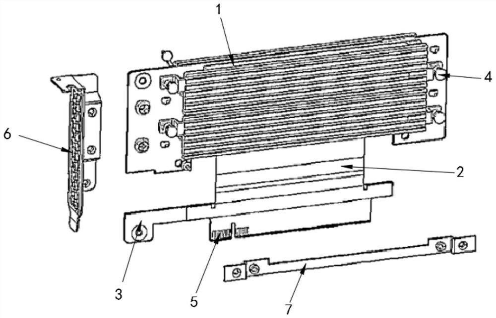
[0033] see figure 1 , the present invention provides a PCIE expansion card, including a motherboard card 1, a flexible circuit board 2 and a signal adapter card 3;

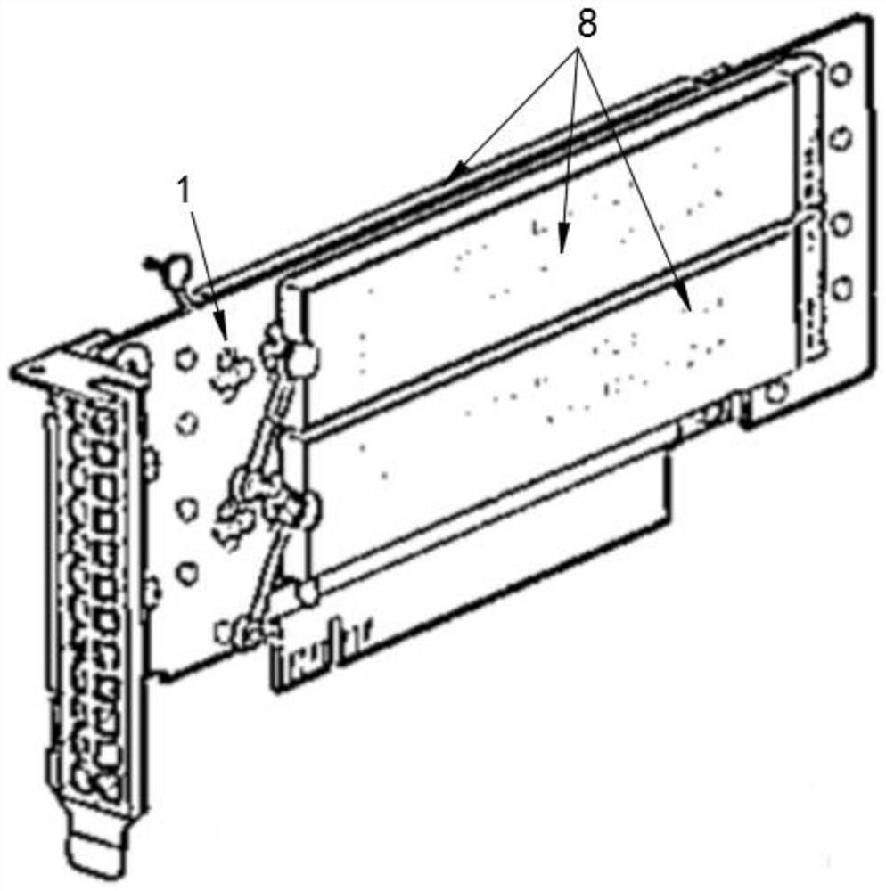
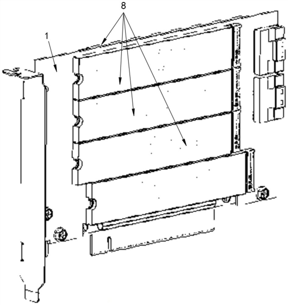
[0034] Both the front and the back of the motherboard card 1 are provided with interface parts 4;

[0035] One end of the flexible circuit board 2 is connected to the lower end of the motherboard card 1, and the other end of the flexible circuit board 2 is connected to the top of the signal adapter card 3;

[0036] The upper end of the signal adapter card 3 is communicatively connected with the motherboard card 1 through the flexible circuit board 2, and the lower end of the signal adapter card 3 is provided with a golden finger 5 for connecting to a PCIE slot.

[0037] At the same time, the PCIE expansion card also includes a riser card fixing bracket 6 fixed to the signal riser card 3 .

[0038] In addition, the PCIE expansion card also includes a board support frame 7 fixed to one side of the motherboard card...

Embodiment 2

[0045] see figure 1 , the present invention provides a PCIE expansion card, including a motherboard card 1, a flexible circuit board 2 and a signal adapter card 3;

[0046] Both the front and the back of the motherboard card 1 are provided with interface parts 4;

[0047] One end of the flexible circuit board 2 is connected to the lower end of the motherboard card 1, and the other end of the flexible circuit board 2 is connected to the top of the signal adapter card 3;

[0048] The upper end of the signal adapter card 3 is communicatively connected with the motherboard card 1 through the flexible circuit board 2, and the lower end of the signal adapter card 3 is provided with a golden finger 5 for connecting to a PCIE slot.

[0049] At the same time, the PCIE expansion card also includes a riser card fixing bracket 6 fixed to the signal riser card 3 .

[0050] In addition, the PCIE expansion card also includes a board support frame 7 fixed to one side of the motherboard card...

Embodiment 3

[0057] see figure 1 , the present invention provides a PCIE expansion card, including a motherboard card 1, a flexible circuit board 2 and a signal adapter card 3;

[0058] Both the front and the back of the motherboard card 1 are provided with interface parts 4;

[0059] One end of the flexible circuit board 2 is connected to the lower end of the motherboard card 1, and the other end of the flexible circuit board 2 is connected to the top of the signal adapter card 3;

[0060] The upper end of the signal adapter card 3 is communicatively connected with the motherboard card 1 through the flexible circuit board 2, and the lower end of the signal adapter card 3 is provided with a golden finger 5 for connecting to a PCIE slot.

[0061] At the same time, the PCIE expansion card also includes a riser card fixing bracket 6 fixed to the signal riser card 3 .

[0062] In addition, the PCIE expansion card also includes a board support frame 7 fixed to one side of the motherboard card...


PUM


Abstract

The invention provides a PCIE expansion card and electronic equipment, which relate to the technical field of server storage expansion and comprise a mainboard card, a flexible circuit board and a signal adapter card; interface parts are arranged on the front surface and the back surface of the main board card; one end of the flexible circuit board is connected with the lower end of the mainboardcard, and the other end of the flexible circuit board is connected with the top end of the signal adapter card. The upper end of the signal adapter card is in communication connection with the main board card through the flexible circuit board, the lower end of the signal adapter card is provided with a golden finger used for being connected with a PCIE slot, the position of the main board card inthe PCIE interface card is adjusted through the characteristic that the flexible circuit board or a flexible flat cable can be twisted, and therefore even under the condition of PCIE association specifications, high parts or interface parts can be placed on the front face and the back face of the main board card, and the usable area of the high parts on the PCB is multiplied.

Description

technical field [0001] The invention relates to the technical field of server storage expansion, in particular to a PCIE expansion card and electronic equipment. Background technique [0002] At the Intel Developer Forum (IDF) in the spring of 2001, Intel announced the third-generation I / O technology that replaced the PCI bus, called "3GIO". The specification of the bus is formulated by the AWG (Arapahoe Work Group) supported by Intel. On April 17, 2002, AWG officially announced that the draft of the 3GIO1.0 specification was completed and handed over to the PCI Special Interest Group (PCI-SIG) for auditing. It was officially announced after the audit on July 23, 2002, and was renamed "PCI Express" for short. PCIe. [0003] Since the launch of the 2003 V1.0 version, the PCIe expansion card still holds the No. 1 position in the computer and server market. Even though the transmission speed of PCIe has been doubled, the requirements for the appearance of the card and physica...

Claims


Application Information

Patent Timeline
Patent Type & Authority Applications(China)
IPC IPC(8): G06F13/42
CPCG06F13/4282
Inventor 温炫萤
Owner INSPUR SUZHOU INTELLIGENT TECH CO LTD
Why Eureka
Try Eureka