Magnetic floater production equipment and production method thereof

A technology for production equipment and magnetic floats, applied in the manufacture of inductors/transformers/magnets, conveyor objects, packaging/dipping, etc., can solve the problems of low efficiency of floats and low product consistency, and achieve ingenious design and high yield , the effect of high quality float

Pending Publication Date: 2021-03-09
ZHANGZHOU WANLIDA ZHONGHUAN TECH INC
View PDF0 Cites 3 Cited by
  • Summary
  • Abstract
  • Description
  • Claims
  • Application Information

AI Technical Summary

Problems solved by technology

[0002] Magnetic floats can float in liquids and have magnets. They are widely used in combination with magnetic sensors for liquid level detection in various fields. The production of magnetic floats includes multiple processes such as dispensing, placing magnets, and gland sealing. The efficiency of hand-made floats is not high. High, easy to produce defective products such as leaky floats, and the product consistency is not high

Method used


Image

  • Magnetic floater production equipment and production method thereof
  • Magnetic floater production equipment and production method thereof
  • Magnetic floater production equipment and production method thereof

Examples


Embodiment Construction

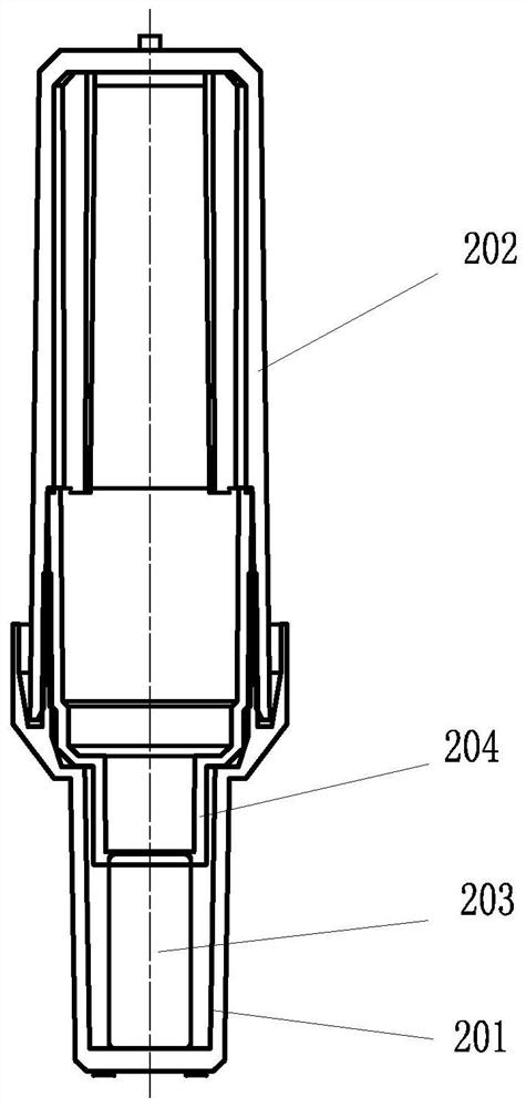
[0033] Please check image 3 , the float includes a bottom cover, a top cover, a magnet and a middle cover. The top cover and the bottom cover are connected to form a accommodating space. The magnet and the middle cover are placed in the accommodating space. The magnet is placed in the bottom cover, and the middle cover is placed in the magnet. Between the top cover and the top cover and both ends abut the top cover and the magnet, under the fixed cover pressure of the top cover and the bottom cover, the middle cover tightly fixes the magnet in the bottom cover and cannot make it move.

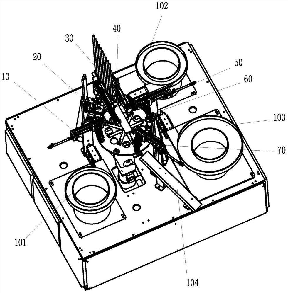
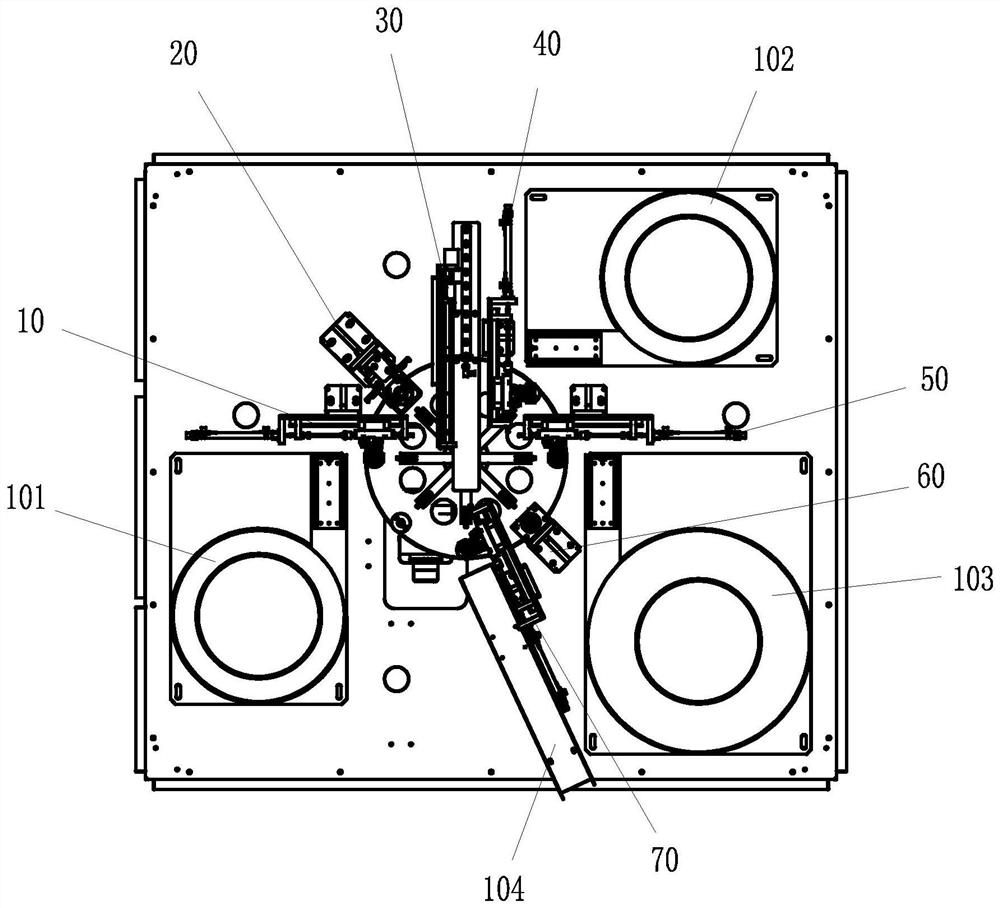
[0034] Please check figure 1 and figure 2 , a magnetic float production equipment, which includes a turntable 100, a bottom cover incoming vibration plate 101, a bottom cover grabbing mechanism 10, a dispensing mechanism 20, a magnet placement mechanism 30, a middle cover incoming material vibrating plate 102, and a middle cover grabbing mechanism The mechanism 40, the top cover incoming vi...


PUM


Abstract

The invention discloses magnetic floater production equipment and a production method thereof. The magnetic floater production equipment comprises: a rotary disc, wherein a plurality of manufacturingstations are distributed in the circumferential direction of the rotary disc at intervals; a bottom cover incoming material vibration disc; a bottom cover grabbing mechanism which can grab the bottomcover and place the bottom cover on the first station; a dispensing mechanism which can be used for gluing the bottom cover; a magnet placing mechanism which can be used for placing a magnet into thebottom cover; a middle cover incoming material vibration disc; a middle cover grabbing mechanism which can grab the middle cover and place the middle cover above the magnet and can enable the middle cover and the bottom cover to be combined in a matched mode; a top cover incoming material vibration disc; a top cover grabbing mechanism which can grab the top cover, can place the top cover above themiddle cover and can enable the top cover and the bottom cover to be combined in a matched mode; a cover pressing mechanism which can be used for tightly pressing the top cover and the bottom cover;a finished product grabbing mechanism which can grab finished products and place the finished products on the discharging channel; and a discharging channel. The magnetic floater production equipmentand the production method thereof have the advantages that automatic production of floaters is achieved, the production efficiency of the floaters is greatly improved, and the yield is high.

Description

technical field [0001] The invention relates to a production equipment, in particular to a magnetic float production equipment and a production method thereof. Background technique [0002] The magnetic float can float in the liquid and has a magnet. It is widely used in liquid level detection in various fields in combination with the magnetic sensor. The production of the magnetic float includes multiple processes such as dispensing, placing the magnet, and sealing the gland. The efficiency of hand-made float is not high. High, it is easy to produce defective products such as leaking floats, and the product consistency is not high. SUMMARY OF THE INVENTION [0003] The present invention provides a magnetic float production equipment and a production method thereof, which overcome the deficiencies of the prior art described in the background art. [0004] The technical scheme adopted by the present invention to solve its technical problems is: [0005] A magnetic float p...

Claims


Application Information

Patent Timeline
Patent Type & Authority Applications(China)
IPC IPC(8): H01F41/00B05C5/02B65G47/52B65G47/90
CPCB05C5/0216B65G47/52B65G47/90H01F41/00H01F41/005
Inventor 林泽勇王艺龙陈江辉郑勇俊陈毅洲
Owner ZHANGZHOU WANLIDA ZHONGHUAN TECH INC
Why Eureka
Try Eureka