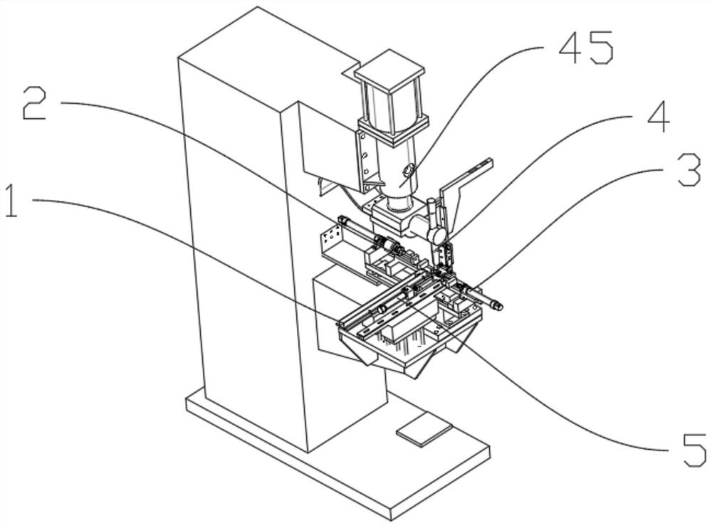
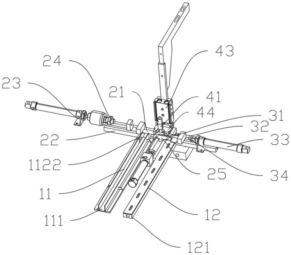
Automatic spot welding working platform for clamping piece nuts

A clip nut and working platform technology, applied in welding equipment, manufacturing tools, resistance welding equipment, etc., can solve the problems of low clip nut spot welding strength, high clip nut scrap rate, and failure to meet production needs, etc., to achieve Improve the quality of spot welding, improve the strength of spot welding, and the effect of good contact

Active Publication Date: 2021-03-12
四川省彭山宏源机电科技开发有限公司
View PDF10 Cites 1 Cited by
  • Summary
  • Abstract
  • Description
  • Claims
  • Application Information

AI Technical Summary

Problems solved by technology

[0003]In the prior art, the clips and nuts are usually spot welded manually, and after the spot welding is completed, the clips and nuts are collected and then transferred to the next process , but the efficiency of manually spot-welding the clips and nuts is low, which is far from meeting the production needs. In addition, when manual spot welding, there are still problems such as low spot welding strength and poor spot welding quality of the clip nuts, resulting in High scrap rate for clip nuts

Method used


Image

  • Automatic spot welding working platform for clamping piece nuts
  • Automatic spot welding working platform for clamping piece nuts
  • Automatic spot welding working platform for clamping piece nuts

Examples


Embodiment Construction

[0051]In order to enable those skilled in the art to better understand the solutions of the present invention, the following will clearly and completely describe the technical solutions in the embodiments of the present invention in conjunction with the drawings in the embodiments of the present invention. Obviously, the described embodiments are only It is a part of embodiments of the present invention, but not all embodiments. Based on the embodiments of the present invention, all other embodiments obtained by persons of ordinary skill in the art without creative efforts fall within the protection scope of the present invention.

[0052] Reference herein to an "embodiment" means that a particular feature, structure, or characteristic described in connection with the embodiment can be included in at least one embodiment of the present invention. The occurrences of this phrase in various places in the specification are not necessarily all referring to the same embodiment, nor ...


PUM


Abstract

The invention discloses an automatic spot welding working platform for clamping piece nuts. The automatic spot welding working platform comprises a feeding assembly, a clamping piece pushing-in assembly, a nut pushing-in assembly, a spot welding assembly and a pushing assembly, wherein the clamping piece pushing-in assembly and the nut pushing-in assembly are arranged on the same straight line andconnected with the feeding assembly at the same time, the spot welding assembly is arranged above the center of the connecting line of the clamping piece pushing-in assembly and the nut pushing-in assembly, the pushing assembly is arranged above the connecting line of the clamping piece pushing-in assembly and the nut pushing-in assembly; a clamping piece pushing air cylinder drives a clamping piece pushing block to push clamping pieces fed into a clamping piece guide groove by the feeding assembly to the position below the spot welding assembly, and a nut pushing air cylinder drives a nut pushing block to push nuts fed into a nut guide groove by the feeding assembly to the position below the spot welding assembly to be subjected to spot welding with the clamping pieces. According to theautomatic spot welding working platform, the clamping pieces and the nuts can be automatically supplemented, automatic spot welding of the clamping pieces and the nuts can be achieved, the spot welding strength of the clamping piece nuts after spot welding is high, the spot welding quality is good, and the rejection rate is low.

Description

technical field [0001] The invention relates to the technical field of welding equipment, in particular to an automatic spot welding work platform for clip nuts. Background technique [0002] figure 1 It is a kind of clip nut, which is widely used in the field of mechanical equipment because of its quick installation function, for example, to install the car license plate on the car body. Among them, the clip nut includes a nut and a clip for installing the nut. There are two protruding notches on the clip, and four sets of spot welding feet are provided at the bottom of the nut. During the processing of the clip nut, welding procedures are included. The side of the clip away from the seam is welded to the spot welding leg of the nut. [0003] In the prior art, the clips and nuts are usually manually spot-welded. After the spot welding is completed, the clips and nuts are collected and then transferred to the next process. However, the efficiency of manually spot-welding t...

Claims


Application Information

Patent Timeline
Patent Type & Authority Applications(China)
IPC IPC(8): B23K11/11B23K11/36
CPCB23K11/11B23K11/36
Inventor 何光洪牟登莹
Owner 四川省彭山宏源机电科技开发有限公司
Why Eureka
Try Eureka