
Building steel cutting machine

A cutting machine and steel technology, applied in the direction of grinding machine parts, grinding machines, grinding/polishing equipment, etc., can solve the problems of rolling accidents of building materials, affecting the operation of workers, and generating a large number of sparks.

Inactive Publication Date: 2021-03-12
王长桂
View PDF1 Cites 0 Cited by
  • Summary
  • Abstract
  • Description
  • Claims
  • Application Information

AI Technical Summary

Problems solved by technology

[0006] Aiming at the deficiencies of the prior art, the present invention provides a construction steel cutting machine, which solves the problem that the violent vibration of the construction materials during the cutting process may cause accidents in the rolling of the construction materials, and at the same time, the cut section of the cut materials is not neat, and the A lot of sparks will be generated, which will affect the operation of workers

Method used

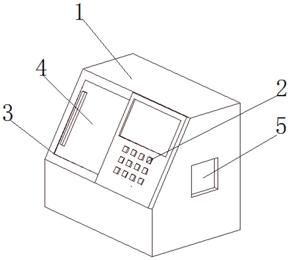

Image

  • Building steel cutting machine
  • Building steel cutting machine
  • Building steel cutting machine

Examples


Embodiment 1

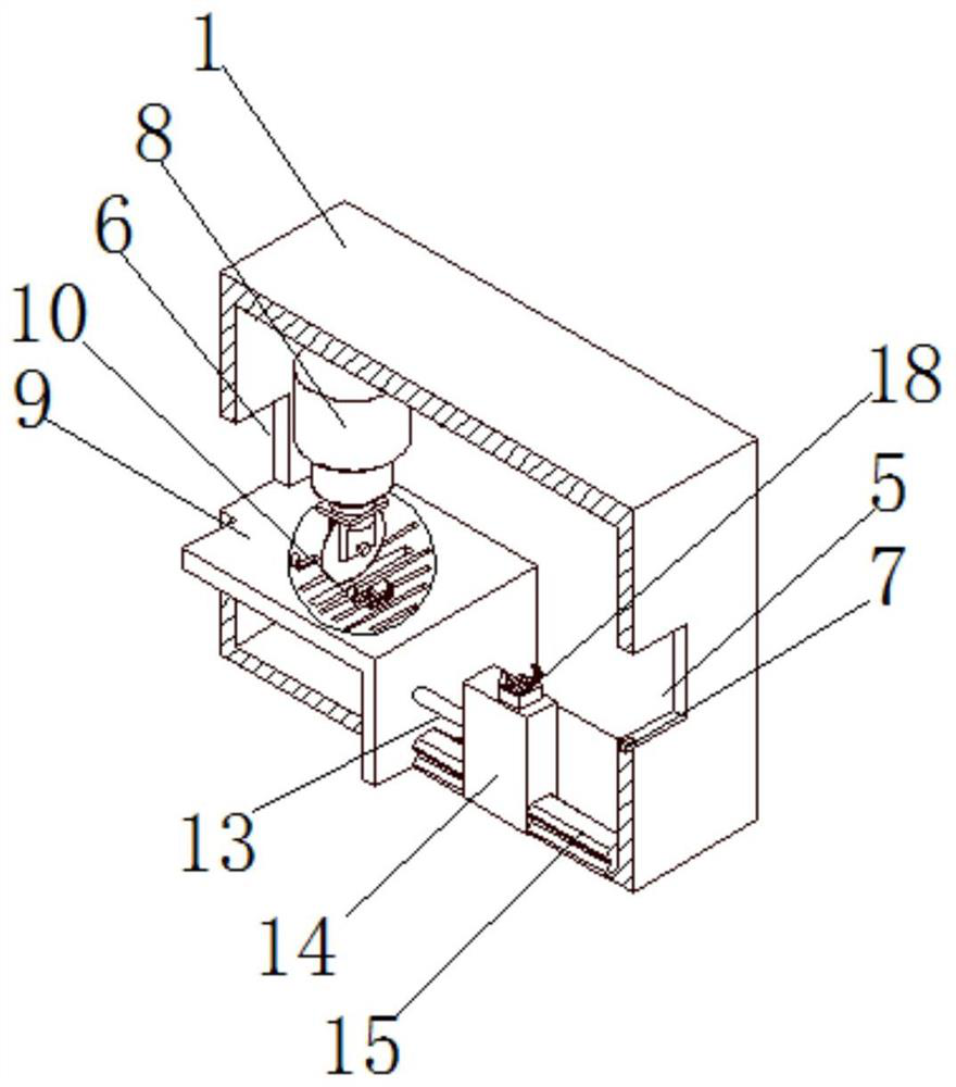
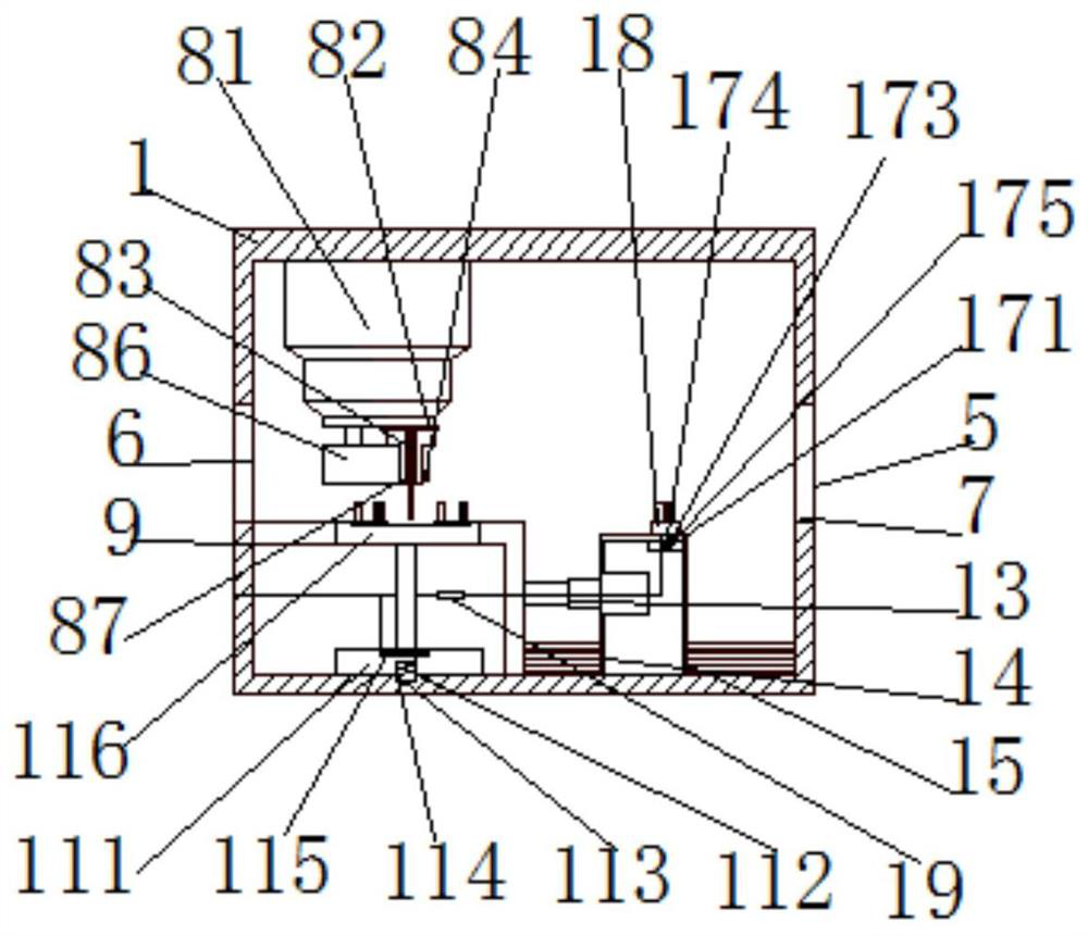
[0035] see Figure 1-3 , the present invention provides a technical solution: a construction steel cutting machine, including a casing 1, a controller 2 is fixedly connected to one side of the casing 1, and a first through slot is opened on the side of the casing 1 close to the controller 2 3. A transparent acrylic plate 4 is slidably connected to one side of the first through groove 3. The first feeding port 5 and the second feeding port 6 are respectively opened on both sides of the casing 1. One side of the first feeding port 6 is provided with a second feeding port. A solenoid valve starts the switch 7, the top of the inner wall of the casing 1 is fixedly connected with a cutting mechanism 8, the bottom of the inner wall of the casing 1 is fixedly connected with a support plate 9, and the top of the support plate 9 is provided with a second through groove 10, the second through groove The inner wall of 10 is rotatably connected with a first rotating mechanism 11, one side ...

Embodiment 2

[0037] see Figure 1-4 On the basis of Embodiment 1, the present invention provides a technical solution: a construction steel cutting machine, the first rotating mechanism 11 includes a first rotating disk 111, and the bottom of the first rotating disk 111 is provided with a first circular groove 112, The top of the inner wall of the first circular groove 112 is rotatably connected with a first fixed rod 113 through a bearing, and the end of the first fixed rod 113 away from the first rotating disk 111 is fixedly connected with a first compression spring 114, and the first compression spring 114 is away from the first fixed rod 113. One end of the rod 113 is fixedly connected with the first rotating disk 111, the inside of the first rotating disk 111 is provided with a first arc-shaped groove 115, and the top of the first rotating disk 111 is fixedly connected with a cutting plate 116 through a connecting rod, and the cutting plate 116 is away from One side of the first rotat...

Embodiment 3

[0039] see Figure 5-7 On the basis of Embodiment 2, the present invention provides a technical solution: a construction steel cutting machine, the clamping mechanism 18 includes a fixed housing 181, and a second motor 182 is fixedly connected to one side of the inner wall of the fixed housing 181, the second The drive shaft of the second motor 182 is fixedly connected with a clamp 183. The clamp 183 includes a clamp shell 1831. One side of the clamp shell 1831 is provided with a fourth through groove 1832. The inside of the clamp shell 1831 is provided with a third arc-shaped groove 1833. One side of the groove 1833 is fixedly connected with an air cushion 1834, and one side of the air cushion 1834 communicates with the air pump 12 through a soft air tube and the second electromagnetic valve 20, and the side of the air cushion 1834 away from the third arc-shaped groove 1832 is fixedly connected with a linkage block 1835, and the linkage One end of the block 1835 away from the...


PUM


Abstract

The invention discloses a building steel cutting machine, and relates to the field of building material cutting. A controller is fixedly connected to one side of a machine shell, a cutting mechanism is fixedly connected to the top of the inner wall of the machine shell, a supporting plate is fixedly connected to the bottom of the inner wall of the machine shell, a second through groove is formed in the top of the supporting plate, a first rotating mechanism is rotatably connected to the inner wall of the second through groove, a telescopic rod is fixedly connected to one side of the supportingplate, a moving block is fixedly connected to the end, away from the supporting plate, of the telescopic rod, a sliding rail is slidably connected to the bottom of the moving block through a slidingblock, a through hole is formed in the top of the moving block, a second rotating mechanism is rotatably connected to the inner wall of the through hole, a clamping mechanism is fixedly connected to one side of the second rotating mechanism, The invention relates to the field of building material cutting. The building steel cutting machine solves the problems that in the cutting process, buildingmaterials violently vibrate to possibly cause accidents of rolling of the building materials, meanwhile, the cut sections of the cut materials are irregular, a large number of sparks are generated inthe cutting process, and operation of workers is influenced.

Description

technical field [0001] The invention relates to the field of building material cutting, in particular to a building steel material cutting machine. Background technique [0002] Construction steel cutting machine is a tool used for cutting steel bars. Generally, there are fully automatic steel bar cutting machines and semi-automatic steel bar cutting machines. It is one of the essential equipment for steel bar processing. It is mainly used in houses. The fixed-length cutting of steel bars in buildings, bridges, tunnels, power stations, large-scale water conservancy projects, etc. has played an important role in various fields of national economic construction. [0003] According to Chinese patent CN107584049A, a construction site steel bar cutting machine is disclosed, which includes a roller holder, a protective case, a motor, a handle, a baffle and a hydraulic rod. Cutting wheel, the outside of the handle is connected with a rotating shaft, the outside of the sliding rod ...

Claims


Application Information

Patent Timeline
Patent Type & Authority Applications(China)
IPC IPC(8): B24B27/06B24B27/00B24B41/00B24B41/06B24B47/00B24B55/00B24B55/04B24B55/06
CPCB24B27/0084B24B27/0683B24B41/007B24B41/06B24B47/00B24B55/00B24B55/04B24B55/06
Inventor 王长桂
Owner 王长桂
Learn More