Large-scale motor rotor shaft turning-over hoisting tool

A technology of large motors and lifting tools, which is applied in the direction of load hanging components, transportation and packaging, etc. It can solve the problems of motors not working normally without any protection and protection measures, affecting motor assembly, etc., to achieve high hoisting efficiency and structure Simplicity and effect of equipment cost reduction

Pending Publication Date: 2021-03-12
STATE GRID CORP OF CHINA +2
View PDF0 Cites 0 Cited by
  • Summary
  • Abstract
  • Description
  • Claims
  • Application Information

AI Technical Summary

Problems solved by technology

During the manufacturing process of the motor, each component needs to be welded and assembled. When dealing with the rotor shaft, it is necessary to turn the rotor shaft in a horizontal state to a vertical state. The existing technology flips the rotor shaft in a horizontal state and a vertical state. When using a crane to lift one end of the rotor shaft, it is difficult to turn over, and it is easy to damage the rotor shaft when directly hoisting, and the hoisting efficiency is low, and the economic benefit is poor; in addition, the flange at the other end of the rotor shaft falls directly, without any protection Protective measures, and the end flange of the rotor shaft is a very precise part, it is easy to damage the flange surface of the rotor shaft end during the flipping process, affecting the assembly of the motor and causing the motor to fail to work normally
Therefore, the existing lifting tool for turning over the rotor shaft has the problems of difficulty in turning over, low hoisting efficiency, and easy damage to the rotor shaft

Method used


Image

  • Large-scale motor rotor shaft turning-over hoisting tool
  • Large-scale motor rotor shaft turning-over hoisting tool
  • Large-scale motor rotor shaft turning-over hoisting tool

Examples


Embodiment

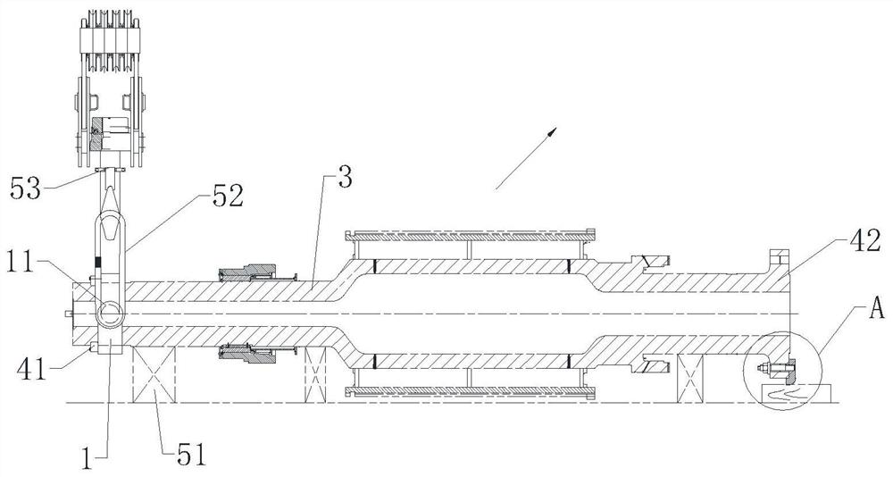
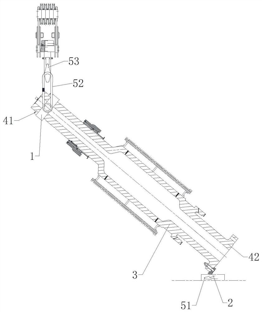
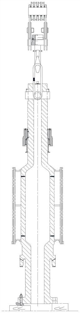
[0024] like Figure 1-7 As shown, the lifting tool for turning over the rotor shaft of a large motor includes a snap ring 1 installed on the neck of the rotor shaft 3 and a turning shoe 2 installed on the grounding side of the bottom end of the rotor shaft 3. The neck of the rotor shaft 3 is provided with a first flange 41 The bottom end of the rotor shaft 3 is provided with a second flange 42, the outer peripheral surface of the snap ring 1 is symmetrically provided with lifting lugs 11, and the top surface of the snap ring 1 is connected with the first flange 41; The bottom surface of the two flanges 42 is connected to the plane part 21, and the bottom end of the plane part 21 is provided with a bent part 22 covering the outer arc surface of the second flange 42, and the bent part 22 is in contact with the outer arc surface of the second flange. Matching, the inward bend between the bent part 22 and the flat part 21 is a right-angle transition area 23 that fits the corner of...


PUM


Abstract

The invention discloses a large-scale motor rotor shaft turning-over and hoisting tool which comprises a clamping ring mounted on the neck portion of a rotor shaft and a turning-over boot mounted on the grounding side of the bottom end of the rotor shaft, wherein the neck portion of the rotor shaft is provided with a first flange, the bottom end of the rotor shaft is provided with a second flange,lifting lugs are symmetrically arranged on the outer circumferential surface of the clamping ring, and the top surface of the clamping ring is connected to the first flange; the turning-over boot comprises a plane part connected to the bottom surface of the bottom surface of the second flange, a bent part wrapping the outer arc face of the second flange is arranged at the bottom end of the planepart, a right-angle transition area attached to the corner of the second flange is arranged at the inner bent position between the bent part and the plane part, and a fillet transition area protrudingoutwards is arranged at the outer bent position between the bent part and the plane part. The large-scale motor rotor shaft turning-over and hoisting tool has the characteristics of being easy to turn over, high in hoisting efficiency and not prone to damage the rotor shaft.

Description

technical field [0001] The invention relates to a turning and lifting tool for a rotor shaft, in particular to a turning and lifting tool for a rotor shaft of a large motor. Background technique [0002] The rotor is one of the important parts of the large-scale generator motor of the pumped storage power station, and the rotor shaft is an important part of the rotor, and its function is to fix the yoke and generate the moment of inertia. During the manufacturing process of the motor, each component needs to be welded and assembled. When dealing with the rotor shaft, it is necessary to turn the rotor shaft in a horizontal state to a vertical state. The existing technology flips the rotor shaft in a horizontal state and a vertical state. When using a crane to lift one end of the rotor shaft, it is difficult to turn over, and the rotor shaft is easily damaged when directly hoisted, and the hoisting efficiency is low, and the economic benefit is poor; in addition, the flange at...

Claims


Application Information

Patent Timeline
Patent Type & Authority Applications(China)
IPC IPC(8): B66C1/12B66C1/62B66C13/08
CPCB66C1/12B66C1/62B66C13/08
Inventor 蒋友凯黄祖光周嘉元王海涛胡浩田鹏韩刘山吕兵郑树伟邹延广吴颖王冰力张政林子枫徐威梁博汪孟成侯晓宇李龙龙王自友李兵
Owner STATE GRID CORP OF CHINA
Why Eureka
Try Eureka