Alloy copper pipe annealing device and alloy copper pipe annealing treatment method

A copper tube and annealing technology, applied in heat treatment furnaces, heat treatment equipment, furnace types, etc., can solve the problem of inability to detect the effectiveness of coiled copper tube purging

Inactive Publication Date: 2021-03-12
海亮奥托铜管(广东)有限公司
View PDF14 Cites 0 Cited by
  • Summary
  • Abstract
  • Description
  • Claims
  • Application Information

AI Technical Summary

Problems solved by technology

[0003] The invention provides an alloy copper tube annealing device and an alloy copper tube annealing treatment method to solve the problem in the prior art that it is impossible to detect whether the purge inside the coiled copper tube is effective during the annealing process

Method used


Image

  • Alloy copper pipe annealing device and alloy copper pipe annealing treatment method
  • Alloy copper pipe annealing device and alloy copper pipe annealing treatment method
  • Alloy copper pipe annealing device and alloy copper pipe annealing treatment method

Examples


Embodiment 1

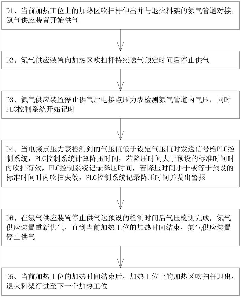
[0034] This embodiment provides an alloy copper tube annealing device, including an annealing furnace, stacker, annealing rack, vacuum device, nitrogen supply device and PLC control system, and the annealing furnace is provided with a vacuum chamber, a transition zone, and a heating zone and cooling zone, the annealing furnace is equipped with conveying roller table and heating device, the annealing material frame moves in the annealing furnace along the conveying roller table, and the annealing material frame is provided with a number of accommodation positions for placing coiled copper pipes, each Nitrogen pipelines are provided on the storage positions, and the feature is that: there are several heating stations in the heating zone, each heating station is equipped with a heating zone purge rod, and the gas inlet of the heating zone purge rod is connected to the nitrogen supply. The device is connected, the gas outlet of the purge rod in the heating area is set opposite to t...

Embodiment 2

[0039] Such as figure 1 As shown, what this embodiment provides is a method for annealing an alloy copper tube, which is characterized in that it includes the following steps:

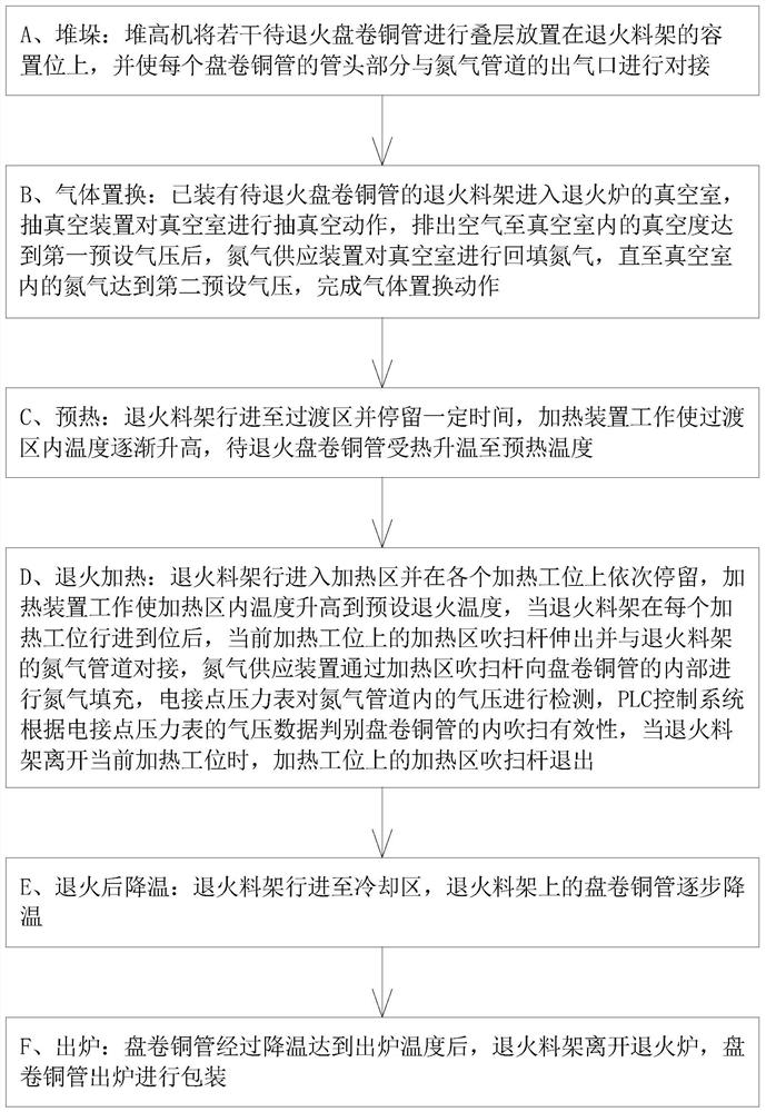
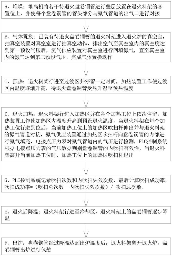
[0040] A. Stacking: The stacker stacks a number of coiled copper tubes to be annealed and places them on the storage position of the annealing rack, and makes the tube head of each coiled copper tube dock with the gas outlet of the nitrogen pipeline ;

[0041] B. Gas replacement: the annealing material rack equipped with coiled copper tubes to be annealed enters the vacuum chamber of the annealing furnace, and the vacuuming device performs vacuuming action on the vacuum chamber, and the air is exhausted until the vacuum degree in the vacuum chamber reaches the first preset air pressure , the nitrogen supply device backfills the vacuum chamber with nitrogen until the nitrogen in the vacuum chamber reaches the second preset pressure to complete the gas replacement action;

[0042] In this embodiment, t...


PUM


Abstract

The invention discloses an alloy copper pipe annealing device and an alloy copper pipe annealing treatment method. The alloy copper pipe annealing device comprises an annealing furnace, a stacking machine, an annealing material rack, a vacuumizing device, a nitrogen supply device and a PLC control system, a conveying roller way and a heating device are installed in the annealing furnace, the annealing material rack moves along the conveying roller way, a plurality of containing positions with nitrogen pipelines are arranged on the annealing material rack, a plurality of heating stations are arranged in the heating area, heating area purging rods are arranged on the heating stations, air inlets of the heating area purging rods are connected with the nitrogen supply device, air outlets of the heating area purging rods are opposite to the nitrogen pipelines, and electric contact pressure gauges are installed on the heating area purging rods. According to the annealing treatment method, inthe annealing process, the electric contact pressure gauges are used for detecting the air pressure in a coiled copper pipe, the inner purging fault problem is reflected and found in time, the process defects that the inner surface of the annealed coiled copper pipe becomes black due to inner purging failure and the like are overcome, the structure is simple, and detection is convenient and effective.

Description

technical field [0001] The invention relates to an alloy copper tube annealing device and an alloy copper tube annealing treatment method. Background technique [0002] Existing alloy copper tube annealing device comprises annealing furnace, stacker, annealing rack, vacuum device, nitrogen supply device and PLC control system, annealing furnace is provided with vacuum chamber, transition zone, heating zone and cooling zone, heating zone There are a number of heating stations inside, each heating station is equipped with a number of purge rods, the purge rods are connected to the nitrogen supply device, the annealing furnace is equipped with a conveying roller table and a heating device, and the annealing rack is annealed along the conveying roller table. Activities in the furnace, the annealing rack is provided with a number of storage positions for placing coiled copper pipes, and each storage position is equipped with a nitrogen pipeline. Before the annealing operation, t...

Claims


Application Information

Patent Timeline
Patent Type & Authority Applications(China)
IPC IPC(8): C22F1/08C21D9/08C21D1/26
CPCC22F1/08C21D9/08C21D1/26
Inventor 余建武
Owner 海亮奥托铜管(广东)有限公司
Why Eureka
Try Eureka